8
ENGLISH
ENGLISH
•Function logics
Behaviour of the automatic system in logics:
A = Automatic E = Semi-automatic
is indicated on Tables 4-5.
•Pause time
Pause time in open state before re-closing, when the automatic
logic is selected.
•Opening/Closing time
Select a movement time enabling the electric motor to receive
power for a few seconds after the automatic system reaches the
mechanical stops.
This is also the maximum time for reaching the limit-switches
(optional items).
•Behaviour of FSW (596MPS only)
Defines the effect of the safety devices being tripped during
closing (immediate reversing or reversing on disengagement).
Note: the 610MPS executes immediate reversing only.
•Failsafe
Failsafe is an electronic system for checking efficiency of the
connected photocells. The check is effected before each closing
activation by the motors, by temporarily cutting power to the
photocell projector (TX) to check the resulting opening of the
contact on the receiver (RX) . If this does not occur, the movement
of the automatic system is disabled for reasons of safety.
To
enable Failsafe, a separate power supply to the photocell
projectors (Fig.12) is necessary.
8
7
654
3
219
8
7
654
3
219
5
4
3
2
1
2
1
TXRX
8
7
654
3
219
8
7
654
3
219
8
7
654
3
219
5
4
3
2
1
2
1
TXRX
8
7
654
3
219
6. EXAMPLES OF SAFETY DEVICE CONNECTIONS
Ü FAILSAFE disabled (SW6=OFF)
J1
J1
J1
J1
J1
J1
Fig. 10
Fig. 11
Fig. 12
Fig. 8
Fig. 9
Fig. 7
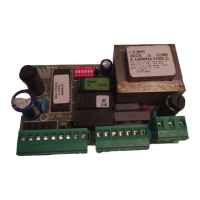
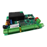
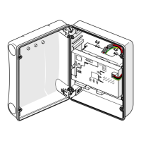
5. START-UP
Install the card by placing it in containers with an adequate
degree of protection. The wiring accessories (cable sleeves,
tubes…) must have the same degree of protection as the
container.
5.1. ROTATION DIRECTION CHECK
1) Cut power to the card
2) Release the automatic system by using the operators lock/
release device.
3) Manually move the automatic system halfway along its
travel.
4) Re-lock the automatic system by using the operators lock/
release device.
5) Restore power to the card.
6) Send an opening pulse (Open) and check if the automatic
system is commanded to open.
If one or both motors are activated at closing, change over their
phases (brown and black cables) on the card terminal board.
No safety device connected
Connection of a safety edge
Connection of a pair of photocells
7. EXAMPLES OF SAFETY DEVICE CONNECTIONS
Ü FAILSAFE enabled (SW6=ON)
TABLE 4 AUTOMATIC LOGIC (A)
LOGIC “A” PULSES
AUTOMATION STATUS OPEN STOP SAFETY DEVICES
CLOSED opens and closes after no effect no effect
pause time (Open inhibited)
OPENING no effect disabled no effect
operating
OPEN FOR PAUSE re-closes disabled stop pause
immediately operating until disengaged
CLOSING re-opens disabled reverses motion
immediately operating (()
STOPPED re-closes no effect no effect
(Open inhibited) (Open inhibited)
TABLE 5 SEMI-AUTOMATIC LOGIC (E)
LOGIC “E” PULSES
AUTOMATION STATUS OPEN STOP SAFETY DEVICES
CLOSED opens no effect no effect
(Open inhibited)
OPENING stops disabled no effect
operating
OPEN re-closes no effect no effect
immediately (Open inhibited) (Open inhibited)
CLOSING re-opens disabled reverses motion
immediately operating (()
STOPPED re-closes no effect no effect
(Open inhibited) (Open inhibited)
(() •596MPS= see SW2 •610MPS=reverses immediately
No safety device connected
Connection of a safety edge
Connection of a pair of photocells