7
ENGLISH
ENGLISH
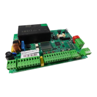
3. WIRING DESCRIPTION
3.1. TERMINAL BOARD J1 (low voltage)
1 = OPEN command (N.O.)
Any device (push-button, detector,…) which, by closing a
contact, supplies an opening or closing pulse to the auto-
matic system.
To install several Open devices, connect N.O. contacts in
parallel.
2 = FSW Closing safety devices contact (N.C.)
Safety devices are all devices (photocells, sensitive edges,
magnetic coils) with N.C. contact, which operate if there is
an obstacle in the area they protect.
Safety devices protect the area affected by the closing
movement of the automatic system.
If the safety devices are tripped during closure, automatic
movement is reversed, whereas they has no effect during
opening. The safety devices operating when the auto-
matic system is open or pausing, prevent closure.
To install several safety devices, connect the N.C. contacts
in series.
ÜIf no closing safety devices are installed, fit a jumper on
this input:
•with terminal 4 (if failsafe is disabled), or
•with terminal 6 (if failsafe is enabled).
3 = STOP command (N.C.)
This is any device (e.g. a push-button) which, by opening
a contact, stops movement of the automatic system.
To install several stop devices, connect the N.C. contacts
in series.
ÜIf Stop devices are not connected, link the input to the
common contact (terminal 4) via a jumper.
4 = Common for contacts/Negative for accessories
supply (-)
5 = Positive for 24 Vdc accessories supply (+)
Max load of accessories: 250 mA.
To calculate absorption values, refer to the instructions for
individual accessories.
6 = Failsafe (-) (see “
4. Programming
”)
If Failsafe is enabled, you must connect the negative poles
of the photocells projectors to this terminal.
7 = FCC Closing limit-switch contact (N.O.)
The closing limit-switch is a device with a N.O. contact
which, by being tripped when the automatic system
reaches the closed position (closing the contact), causes
the automatic system to stop after about 1 second.
8 = Common for contacts/Negative for accessories
supply (-)
9 = FCA Closing limit-switch contact (N.O.)
The opening limit-switch is a device with a N.O. contact
which, by being tripped when the automatic system
reaches the open position (closing the contact), causes
the automatic system to stop.
3.2. TERMINAL BOARD J2 (high voltage)
10-11 = Connection to initial thrust capacitor
If the application has two operators, connect the capaci-
tors in parallel.
12 – 13- 14 = Connection to electric motor
Terminals 12-13 should be connected to the motor phases
(brown and black cables) whereas terminal 14 should be
connected to the motor (blue cable).
If the application has two operators, connect the two
motors in parallel.
15-16 = Timed courtesy light (596MPS)
Flashlight (610MPS)
The function of this output differs according to card model:
•596MPS:
Connect the courtesy light - 230V~ 60W max. - if any. The
courtesy light is activated when the motor starts and stays
lighted for about 90 seconds after end of movement.
•610MPS:
Connect the flashlight - 230V~ 60W max.
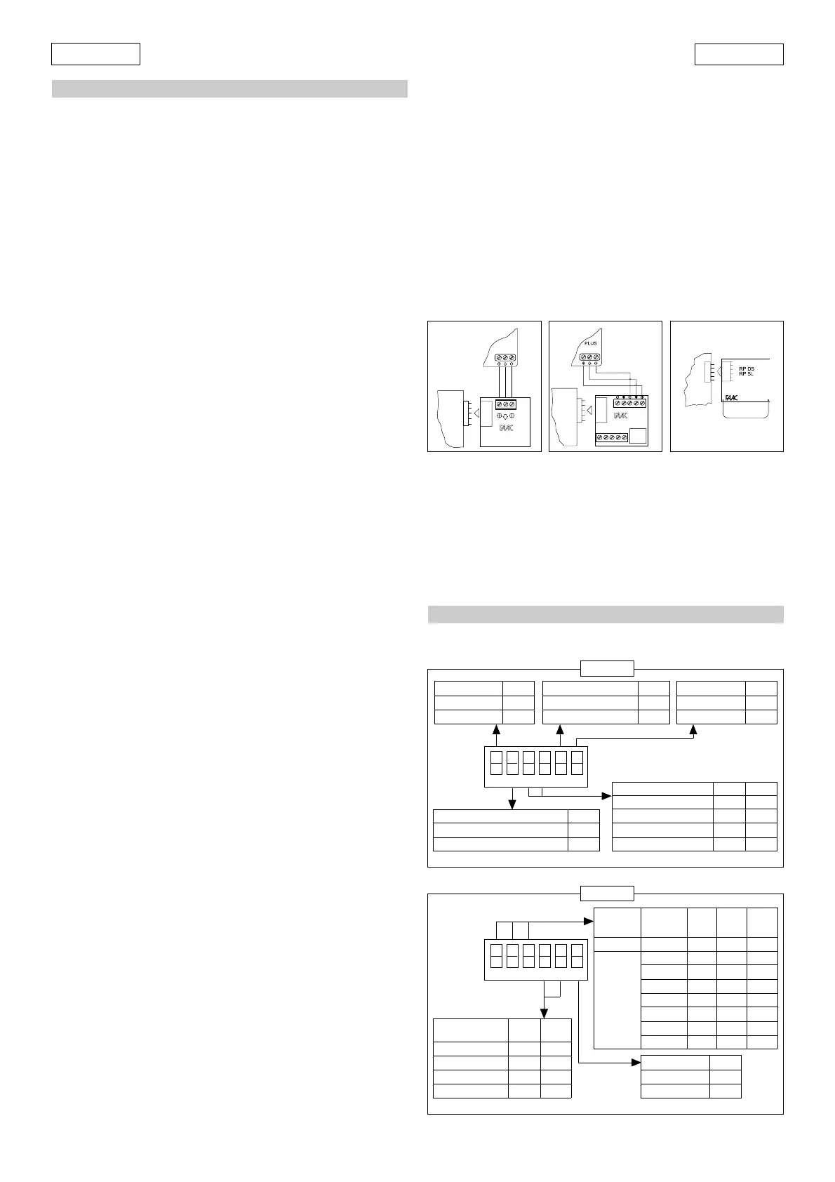
3.3. CONNECTOR J3 (low voltage)
Connector J3 is used for rapid connection of MINIDEC, DECODER,
and RP RECEIVER cards (Fig. 4,5,6)
Install by fitting the accessory cards so that their components side
faces the inside of the electronic appliance.
Insert and remove the cards after cutting power.
3.4. CONNECTOR J4 (low voltage)
The J4 connector is used for rapid connection of the opening push-
button on the up-and-over operators’ housing.
3.5. TERMINAL BOARD J9 (high voltage)
Terminal board for connecting 230V~ 50Hz power supply.
[L=Line - N=Neutral - W= Ground].
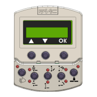
4. PROGRAMMING
To programme operation of the automatic system, turn the
microswitches as follows:
Op/Clos. time (sec.) SW3 SW4
40 OFF OFF
35 ON OFF
30 OFF ON
25 ON ON
Behaviour FSW SW2
opens immediately OFF
opens when disengaged ON
123456
ON
OFF
Failsafe SW6
No OFF
Yes ON
Pause time (sec.) SW5
30 OFF
60 ON
Logic SW1
E OFF
AON
596MPS
123456
ON
OFF
Logic Pause SW1 SW2 SW3
(sec.)
E / OFF OFF OFF
0 ON OFF OFF
2 OFF ON OFF
5 ON ON OFF
A 10 OFF OFF ON
15 ON OFF ON
30 OFF ON ON
60 ON ON ON
Op/Clos. time SW4 SW5
(sec.)
4 OFF OFF
5 ON OFF
7 OFF ON
9ONON
Failsafe SW6
No OFF
Yes ON
610MPS
MINIDEC
SL/DS
PLUS
844MPS
DECODER
SL/SLP/DS
844MPS
Fig.4 Fig. 6Fig. 5