22
+NC COMNO
LOCKFSWTX W.LIGHT30 Vcc FSW STOP
9 10 11 12 13 14 15 16 17 18 19 20 21 22 23 24 25
+OPCL—NCB A ————— + +—
–
4 Wire
Receiver
Figure 19. Connect a four-wire receiver
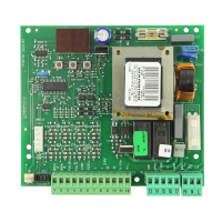
Decoder Card: If you are installing the Digicard
magnetic card reader, or the Digikey keyboard, use the
quick-fit connector J4 for the DS (formerly the MD01)
decoder card (see Figure 13).
Open/Hold Open Device: To open and hold open the
gate, an Open/Hold Open device must make a set of
contacts across terminals 18 and 19 (or 16 and 17) and
must break a set of contacts between terminals 13 and
21 (see Figure 20).
Stop Button: The stop button you install must have
normally closed (N.C.) contacts. Multiple stop buttons
must be wired in series. Connect your stop device
between terminals 14 and 15.
Note: If you choose not to install a stop button,
you must install a circuit between these
terminals for the control panel to work.
The LED Indicators: The five light-emitting diodes
(LEDs) on the control panel can be used to check for
the proper functioning of the devices you attach to the
control panel. The LED lights are on whenever the
contacts are closed across each of the respective
terminals.
LOCKFSWTX W.LIGHT30 Vcc FSW STOP
9 10 11 12 13 14 15 16 17 18 19 20 21 22 23 24 25
+OPCL—NCB A ————— + +—
Relay
24 VDC
SPDT
Switch
NC
NO
COM
Figure 20. Connect an Open/Hold Open device
with an external relay
DL1 and DL2 should illuminate only when an
activating signal is sent for 2 and 1 gate leaves,
respectively. DL3 should be illuminated except when
the stop button is pressed. DL4 and DL5 should be
illuminated except when the reversing devices, for
opening and closing, respectively, are triggered. Use the
LEDs and the table below to determine if the accessory
devices you have installed are operating properly.
LED On Off
DL1,
Open 2 leaves
Command
active
Command
inactive
DL2,
Open 1 leaf
Command
active
Command
inactive
DL3, Stop Command not
active
Command
active
DL4,
FTSW Open
Opening
reversing
devices not
triggered
Reversing
device triggered
DL5,
FTSW Close
Closing
reversing
devices not
triggered
Reversing
device triggered
Electric Lock: An electric lock can make use of the
reversing stroke function controlled by DIP switch 5. A
reversing stroke is a short closing phase that allows the
electric lock time to disengage itself before the operator
starts its opening. Use DIP switch 5 if necessary for
your lock to function correctly. Connect your lock to the
terminals 24 and 25. The terminals provide 12 VAC
pulsed power.
Connect a magnetic locking device as shown in Figure
21, below.
Warning Light: Connect a warning light to terminals
22 and 23 in the group labeled W.LIGHT in terminal
block J3. The terminals provide an output voltage of 30
VDC, maximum power 3 Watts. This output voltage
will power most 24 VDC warning lights.
Relay
24 VDC
SPDT
Mag
Lock
+
NC
COM
–
LOCKFSWTX W.LIGHT30 Vcc FSW STOP
9 10 11 12 13 14 15 16 17 18 19 20 21 22 23 24 25
+OPCL—NCB A ————— + +—
Figure 21. Connect a mag lock to the 450 MPS
control panel