18
1 2 3 4 5 6 7 8 9 10 11 12 13 14 15 16 17 18 19 20 21 22 23 24 25
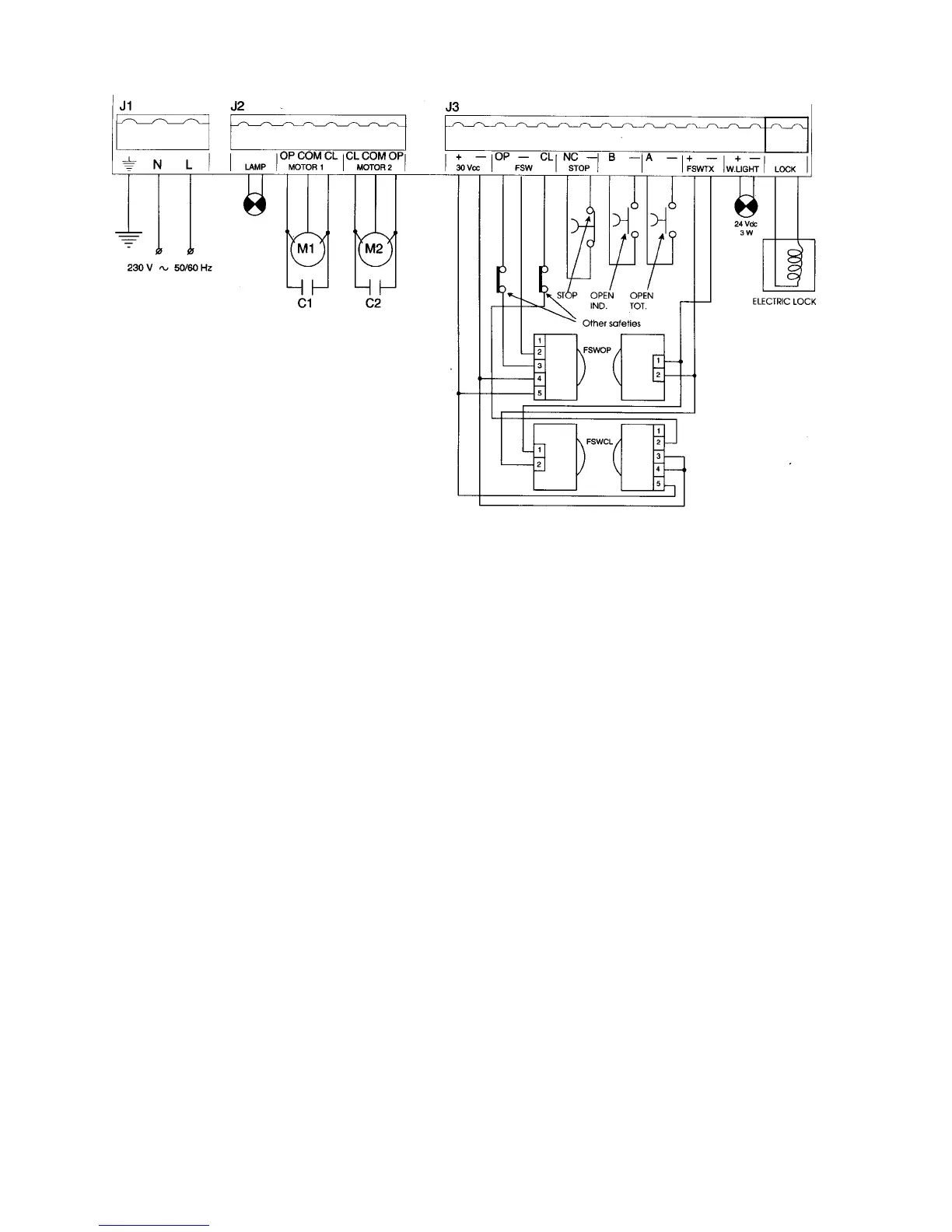
Figure 14. The terminal strip wiring of the 450 MPS
Connect the Operator(s) to
the Control Panel
WARNING! Turn the main power off before
you make any electrical connections or set any
switches inside the control panel box.
Using a Junction Box
Connecting your operator(s) to the control panel may
require the use of one or more junction boxes. Whether
you need 0, 1, or 2 U.L. Listed junction boxes depends
on your gate design (refer to Figure 15 below).
Note: The 750 Operators shipped for U.L.
applications come with a U.L. listed junction
box installed in the power unit box.
If any operator is more than 2 ft away from the U.L.
Listed control panel enclosure, the connection must be
made inside a junction box. Use a U. L. Listed cord grip
where the operator cord enters the junction box; use
conduit between the junction box and the enclosure.
Connecting the Operator(s)
Caution: Do not use the terminal connections
for Motor 2 (terminals 6, 7, and 8) if yours is a
one-leaf gate design.
Note: If you have a one-leaf gate design, the
operator must be connected to Motor 1
(terminals 3, 4, and 5).
If your gate system has one operator, connect the
capacitor and the brown and black (or red and black)
wires from your operator to the terminals 3 and 5 in
block J2 for Motor 1. Connect the blue (or white) wire
from the operator to terminal 4 for Motor 1.
Note: If you want to delay the closing of one
gate leaf in a two-leaf gate design, be sure to
connect its operator to Motor 1 (terminals 3, 4,
and 5).
If your gate system has two operators, connect the
second operator to terminals 6, 7, and 8 in block J2 for
Motor 2. Connect the capacitor and the brown and black
(or red and black) wires from the operator to terminals 6
and 8, and connect the blue (or white) wire from the
operator to terminal 7 for Motor 2.
Adjust the Pressures
for the Operator
WARNING! You must decrease the pressures
of the gate’s opening and closing momentum
before you operate the gate electrically. The
pressure valves are not preset at the factory and
may operate the gate leaf with enough force to
endanger people and seriously damage the gate
leaf itself.
NOTE: In order to comply with UL 325, two sets of
FAAC photocells must be installed. One set should be 6
inches outside the closed gate(s) and act as a closing
reversing device. Another set should be 6 inches beyond
the swing of the gate and act as an opening reversing
device. The installer is responsible for determining the
appropriate mounting height.