19
To the U. L. Listed
gate operator
To the U.L. Listed
control panel
Conduit to
U.L. Listed
control panel
enclosure
according to
N.E.C.
U.L.Listed
cord grip
Junction box
Op.
1
Op.
2
1 2 3 4 5 6 7 8
OP COM CL CL COM OP
Lamp Motor 1 Motor 2
J1 J2
High-voltage
terminal strip
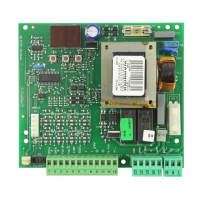
450 MPS Control Panel
U.L. Listed Control Panel Enclosure
Cord grip or conduit from U.L.
Listed gate operator(s) (see text)
Ground
Legend
Red
Black
White
Yellow/
Green
(a)
(b)
J3
Figure 15. Wiring detail (a) inside the junction box and (b) from the junction box or operator to the
high-voltage terminal strip on the 450 MPS control panel
Hydraulic
power
unit
Receptacle for hydraulic pipe fitting
Bypass valves
Red: Closing pressure
Green: Opening pressure
Figure 16. The bypass valves on the front of the power unit