17
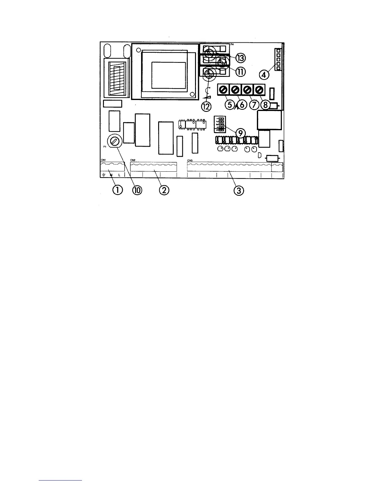
1 J1 terminal block for main power supply 8 Leaf delay potentiometer
2 J2 terminal block for connecting the operator(s) 9 DIP switch assembly
3 J3 terminal block for low-voltage accessories
Fuses 220 VAC 115 VAC
4 J4 quick connector port 10 F1, Main power 5 A 10 A
5 Pressure adjustment potentiometer 11 F2, Accessories 800 mA 800 mA
6 Pause time potentiometer 12 F3, Electric lock 1.6 A 1.6 A
7 Potentiometer for adjusting open/close time 13 F4, Microprocessor 250 mA 250 mA
Figure 13. The 450 MPS control panel
Connect the ground to the grounding terminal in block
J1 and connect the power wires to the terminals labeled
N (neutral) and L (phase).
Caution: The operators are grounded only by
the grounded circuit the installer provides.
Connect One
Activating Device
WARNING! Turn the main power off before
you make any electrical connections or set any
switches inside the control panel enclosure.
For the purposes of installation you need to connect at
least one normally open (N.O.) activating device for
your operator(s).
• If you have a two-leaf gate design,
connect the activating device to terminals
18 and 19.
• If you have a one-leaf gate design, connect
the activating device to terminals 16 and
17.
You use this activating device in the rest of the
installation process. You can connect additional
activating devices later.