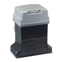
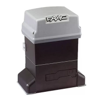
The 750 is an automatic gate operator for a swinging gate leaf.
It makes possible to automate gates in a virtually invisible way
The operator is a two piece unit consisting of a hydraulic control
unit (pump) and a hydraulic drive unit which are connected by
the means of two hydraulic hoses.
The 750 Operator also includes a key operated Manual Release
mechanism and two bypass valves that precisely control the
force applied to the gate leaf through the operator.
The 750 operator is designed and built to automate vehicular
swing leaf gates. Do not use for any other purpose.
1 DESCRIPTION AND TECHNICAL SPECIFICATIONS
Tab.1 - Technical Specifications for hydraulic control unit
Input voltage
115Vac (+10% -6%) or
230Vac (+6% -10%)
Power
220W
Current
2A (115V) - 1A (230V)
Electric motor speed 1400 rpm
Thrust capacitor 25 uF (115V) - 8uF (230V)
Thermal protection 248°F (120°C)
Use frequency (cycles/h) (1)
45 cycles/hour
Oil quantity
1.05 Qt (1 l)
Oil type FAAC HP OIL
Operating ambient temperature 4°F +131°F (-20 °C +55°C)
Protection class IP 55
Weight 16.5 lb (7.5Kg)
Pump capacity 0,75 (l/min)
Max leaf length 13 ft (4 m)
Min leaf length 8 ft (2.4 m)
(1) Exposure to direct sunlight can determine a drop in use
frequency.
750 OPERATOR
MODELS 100° 180°
Max leaf weight 1760 lb (800Kg)
Max rotation angle
118
°
200
°
Max torque
400 lbf (543Nm)
Angular speed 7.8° / sec
Oil quantity 0.31 Qt (0.3 l) 0.53 Qt (0.5 l)
Protection class IP 67
Weight
17.6 lb (8Kg) 19.8 lb (9Kg)
Tab.2 - Technical specifications for hydraulic drive unit
1
2
Always separate low voltage wiring from AC power cables. Use
separate conduits to avoid electrical interference.
The installer is responsible for grounding the gate and operator
systems, for providing the main power breaker switch, and for
making sure that the entire gate system meets all applicable
electrical codes.
Make sure to locate all controls that operate the gate system
at least 6 ft away from any moving parts.
a Oil plug / Dip Stick
b Vent screw
c Manual release lever
d By-pass valve screws
e Hydraulic connection fittings
f Air bleed screws
g Levelling set bolts
6