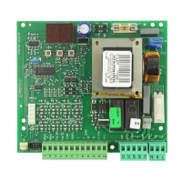
24
Figure 24. Turn the adjustment screw
clockwise to increase the braking intensity
and counter-clockwise to decrease the
braking intensity
The brass rod that extends from the plastic gear
assembly and out of the black plastic housing has a 6-
mm hex head on the visible end. You need to slide this
hex head into the brass fitting of the 760 Operator that is
located on the same end as the bypass valve adjustment
screws (see Figure 29).
Brass gear
assembly
Plastic gear
assembly
Figure 25. Assemble the Manual Release
mechanism
Once the head is seated, the rest of the Manual Release
assembly should fit into place on the top of the 760
Operator. Use the four screws in the parts package to
hold the Manual Release housing in place.
Figure 26. Install the Manual Release
mechanism
 Loading...