770 N 3 732615 - Rev.A
ENGLISH
Translation of the original instructions
Thank you for choosing our product. FAAC S.p.A. is sure you will get the
performances you expect to satisfy your requirements. All our products
are the result of a many years’ experience in the field of the automated
systems.
In the middle of the manual you will find a detachable booklet
containing all the images for the installation.
1. IMPORTANT WARNINGS FOR THE INSTALLER
• Carefully read the whole manual before beginning to install the ope-
rator.
• Store the manual for future reference.
• The correct operation and the declared technical specifications are
only valid if the instructions given in this manual are strictly observed
and only FAAC S.p.A. accessories as well as safety device are used.
• Due to the lack of a mechanical clutch, it is necessary to use a control
unit with an adjustable electronic clutch.
• The automated system was designed and built to control vehicle
access. Avoid any other use.
• The operator cannot be used to move safety exits or gates installed
on emergency routes (escape routes).
• Do not transit when the gate is moving.
• If the leaf you wish to motorise features a built-in door for pedestrian
passage, the door must be equipped with a safety switch in order to
disable operation of the gate when the door is open.
• Anything not expressly specified in this manual is not permitted.
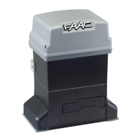
2. DESCRIPTION OF THE COMPONENTS
With reference to the fig.1
Pos. Description
Supporting box
Operator
Gate support frame
110° manoeuvre lever system
140° manoeuvre lever system (optional)
Release device
Cover
Draining hole
Cable routing holes
Lubrication hole
3. TECHNICAL SPECIFICATIONS
Model 770 N 230V 24V
System power supply 230V~ 50Hz
Motor power supply
230V~
50Hz
24V
"
Thermoprotection (°C) 140 /
Capacitor (μF) 12.5 /
Absorbed power (W) 380 70
Max. torque (Nm) 330 330
Nominal torque (Nm) 220 200
Opening angle (°)
110
(140 and 180 with kit)
Angular speed (°/sec.) 66
Max leaf length (m)
3.5 (110°) - 3 (180°) - 2.5
(140°)
Max leaf weight See fig.2
Usage frequency and type S3 30% 100%
Protection class IP 67
Noise level dB(A) <70
Operating temperature (°C)
-20 +55
Weight (Kg)
Operator (kg)
12,5
Supporting box (kg) 15.3
Operator dimensions (mm) 362 x 153 H 127
Supporting box dimensions (mm) See fig.3
Values obtained from laboratory testing.
4. INSTALLATION
Max usage curve
The curve (fig.4) makes it possible to identify the maximum operation
time (T) depending on the frequency of use (F) for 230V~ motors.
To guarantee good operation it is necessary to remain within the work
range below the curve.
The curve is obtained at a temperature of 20°C. Exposure to direct
sunlight can determine a drop in usage frequency up to 20%.
HOW TO CALCULATE THE USAGE FREQUENCY
Ta + Tc
%F=
x100
Ta + Tc + Tp + Ti
Ta = opening time
Tc = closing time
Tp = pause time
Ti = interval between one complete cycle and the next
4.1 ELECTRICAL PREPARATIONS (STANDARD SYSTEM)
With reference to the fig.5:
Pos. Description Cable Nr. and Diam.
Gearmotor
230 V~ 4x1.5mm
2
24 V
"
2 x see table
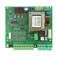
Control unit (system power supply) 3x1.5mm
2
TX Photocells 2x0.5mm
2
RX Photocells
4x0.5mm
2
2x0.5mm
2
(BUS)
Key switch 2x0.5mm
2
Flashing lamp 2x1.5mm
2
For cable installation, use adequate rigid and/or flexible tubes.
Separate the 230 V~ power cables from the low-voltage ones.
24V MOTOR CABLE DIAMETER
Operator - Board distance
Up to 15 m From 15 m to 25 m From 25 m to 35m
Conductor
diameter
2.5 mm
2
4 mm
2
6 mm
2
4.2 PRELIMINARY CHECKS
1. The mechanical elements used for construction must comply with
EN 12604 and EN 12605 Standards
.
2. The
leaf structure must be suitable for automation.
3. Minimum distance between the lower edge of the leaf and the floor, as
shown in fig.6.
4. Presence of mechanical leaf limit stops.
5. Check
for the presence of only the upper hinge.
The condition of the structure directly affects the reliability
and safety of the automated system.
Before installing the automated system, carry out any necessary
smith work on the gate.
4.3 INSTALLING THE SUPPORTING BOX
1. Choose the orientation of the box according to the dimensions shown
in
fig.7 and 8.
2. Dig a hole to position the supporting box
(fig.9).
Modify the dimensions of the hole based on the type of ground (the
dimensions in fig.9 refer to the minimum dimensions of the hole).
3. Position the box as shown in fig.10.
4. Place a rigid tube or a flexible sheath for passage of the power supply
cables, fig.11 ref..
5. Place a tube for draining rain water, fig.11 ref..
6. Ensure that the box is walled-in flat.
4.4 INSTALLING THE LEAF
1. Create a leaf containment frame as shown in fig.12.
2. Determine the position of the leaf based on the rotation axis.