2
ENGLISH
1 WARNINGS
Attention: Before attempting any work on the control board (connections, maintenance), always turn off
power.
- Install, upstream of the system, a differential thermal breaker with adequate tripping threshold,
- Connect the earth cable to the terminal on the J1 connector of the board (see fig. 1).
Always separate power cables from control and safety cables (push-button, receiver, photocells).
To avoid any electrical disturbance, use separate sheaths or a screened cable (with the screen earthed).
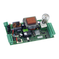
The E550 control board was designed to command the opening of up-and-over doors with one or two motors.
Thanks to encoder control and opening and closing limit switches, if correctly used, it can guarantee installation in
conformity with current safety regulations.
The E550 SLAVE control board is an interface for the second motor, on which the courtesy light is also installed.
CONTROL BOARD E550
4 E550 LAY-OUT AND COMPONENTS
Power supply voltage
Vac (+6% -10%) / Hz.
230 / 50.
Absorbed power (W) 12
Max motors load (W) 800
Power supply
for accessories (Vdc)
24
Accessories max.current (mA) 300
Operating ambient temperature (°C)
-20 / +55
Protective fuses mains / accessories circuit
Rapid connector
Coupling to 5-pin Minidec board
Decoder, Receiver, RP/RP2
Terminal board inputs
(removable)
Open / Encoder / Opening safety
devices / Closing safety devices /
Opening limit switch / Closing limit
switch / Flashing light 230 Vac - 60W.
Terminal board outputs (removable)
Motor/Outside courtesy light 230 Vac
/ 24 Vdc power supply to accessories
Max load for integrated courtesy
light (W)
25
Max load for outside courtesy
light (W)
250
2 TECHNICAL SPECIFICATIONS
4.1 DESCRIPTION OF COMPONENTS
F1 FUSE 5x20 5A/250V (mains circuit)
F2 FUSE 5x20 500mA / 250V (accessories)
J1 TERMINAL-BOARD for 230 Vac power input
J2
TERMINAL-BOARD motor output, flashing light and ext. courtesy
light
J3 TERMINAL-BOARD: Low voltage inputs / accessories
J4 Rapid CONNECTOR: DECODER MINIDEC / RP RECEIVER
P1 “+” PUSH-BUTTON for programming
P2 “-” PUSH-BUTTON for programming
P3 “F” PUSH-BUTTON for programming
DL DISPLAY for signals and programming
LP1 Courtesy LIGHT 25W 230Vac E14
TF1 TRANSFORMER
Fig. 1
Logic Automatic / Semi-automatic
Pause Time
Programmable from 0 to 4 min. (default 2 min.)
Max. thrust torque YES / NO
Fail Safe YES / NO
Pre-flashing
Programmable from 0 to 10 sec. (default 0 sec.)
Electronic clutch Programmable on 50 levels
Limit switch intervention
mode
2 types of operating modes
Courtesy light timer
Programmable from 0 to 4 min. (default 30 sec.)
Safety devices tripping
mode
3 types of operating modes
3 OPERATING PARAMETERS

 Loading...