7
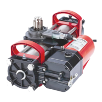
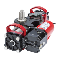
FAAC Model S418 Swing Gate Operator
Technical Specications S418
Power Supply (VDC) 24
Nominal Power (W) 35
Absorbed Current (A) 1.5
Maximum Thrust Force (daN) 180
Stroke (inches) 17.75
a
Speed (inches/sec) 0.75
Maximum Size of Leaf (inches) 106
b
Type and Frequency of Use at 68°F 80 cycles/day
Consecutive Cycles at 68°F 30
Ambient Operating Temperature (°F) -4 to 131
Operator Weight (lbs) 13.2
Protection Class IP54
Operator Dimensions See g. 2
a
If you do not wish to use the mechanical stops on opening
and closing, the operator stroke becomes 15.25 inches.
b
With leaves of over 90.5 inches, an electric lock must be
installed to ensure locking of the leaf.
2. TECHNICAL SPECIFICATIONS
3. INSTALLATION
When laying electrical cables, use conduits with
adequate rigidity and/or exibility.
To avoid any type of interference, we advise you
to always separate low-voltage accessories and
command connection wiring from power supply cables,
use separate sheaths.
3.2 PRELIMINARY CHECKS
The structure of the gate directly inuences the reliability
and safety of the automated system. To ensure correct
operation, the structure of the existing gate, or that to be
tted, must have the following characteristics:
• The length of leaf must conform to what is shown in the
technical characteristics of the operator (Section 2).
• The structure of the leaves must be sturdy and rigid,
suitable for an automated system.
• There must be regular and uniform movement of the
leaves, with no friction or sticking along their entire
movement.
• Hinges must be suitably sturdy and in good condition.
• Mechanical opening and closing stop-points must be
present on the ground (not necessary if mechanical
operator stops are used).
It is recommended that any metalwork operations
should be performed prior to installing the automated
system.
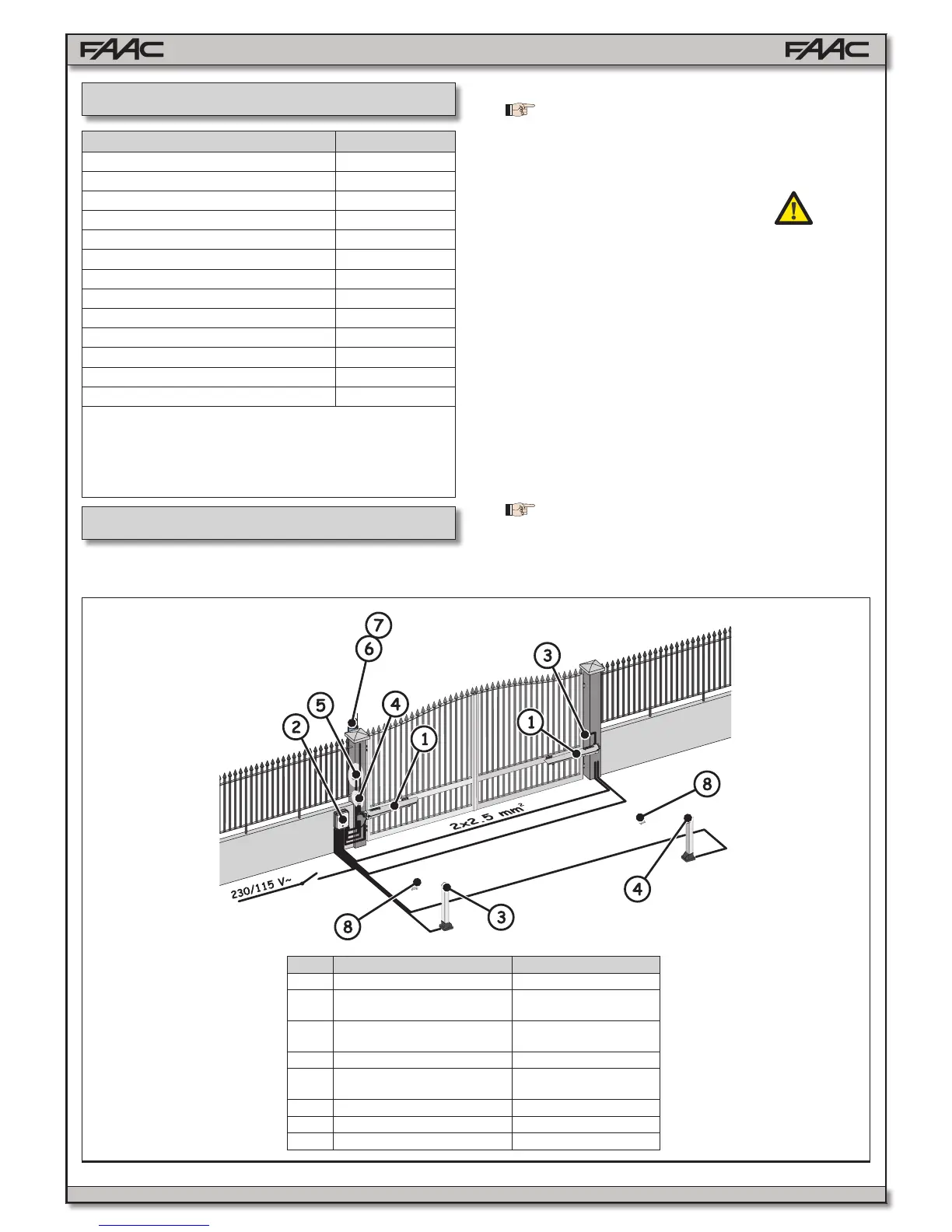
3.1 ELECTRICAL PREPARATIONS SETUP
Fig. 3
Part Description Cables
1 Operators Supplied
2 Control Unit
3x1.5 mm
2
(Power Supply)
3 TX Photocells
4x0.5 mm
2
(2x0.5 mm
2
Bus)
4 RX Photocells 2x0.5 mm
2
5 Key Selector
2x0.5 mm
2
(1 contact)
3x0.5 mm
2
(2 contacts)
6 Flashing Lamp 2x1.5 mm
2
7 External Antenna Coaxial Cable
8 Mechanical Stops