8
FAAC Model S418 Swing Gate Operator
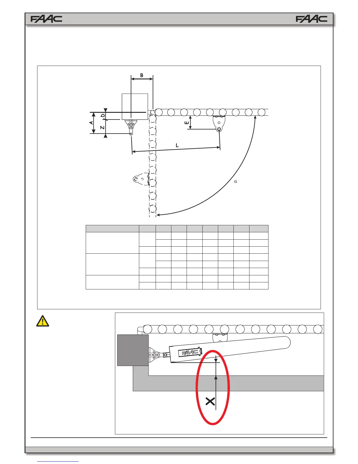
3.3 INSTALLATION DIMENSIONS
Determine the assembly position of the operator, referring to Figure 4 and related table. It is a good idea at this stage to choose
whether or not you want to use the built in mechanical positive stops; eliminating the mechanical stops increases the working stroke of
the operator and values A and B must be changed.
Fig. 4
a
A B C
a
D
b
Z
c
L E
c
With mechanical
stops
90°
6½ 6½ 13 3½ 3 27 4⅛
6⅞ 6⅞ 13¾ 3½ 3⅛ 27 4⅛
110° 6 6 13⅜ 3⅛ 2¾ 27 4⅛
With mechanical
stop
at opening
90°
6⅞ 165 13⅜ 4 3 28 4⅛
7 7 14⅛ 4 3⅛ 28 4⅛
110° 6¼ 6¼ 14⅛ 3½ 2¾ 28 4⅛
With no stops
90° 7 7 14⅛ 4 2¾ 28 4⅛
110° 5⅝ 6⅝ 15 4 2¾ 28 4⅛
a
Working stroke of the operator.
b
Maximum value.
c
Minimum value.
Once the operator has
been installed, check that
the value of “X” in Figure 5
is greater than 20 inches. If the
value of “X” is less than 20 inches.
The area MUST be protected by
an entrapment protection device
complying with Standard UL 325.
Fig. 5
Dimensions in Inches