7 < < < <
UK IRL
3 Instruction for Installation
3.1 Gas connection
Installation pipes should be in accordance with BS 6891. Pipe work from the meter to the
appliance must be of adequate size.
The complete installation including the meter must be tested for soundness and purged as
described in the above code.
A means of isolation must be provide in the supply to facilitate servicing.
The connection should be made in 8 mm copper or similar semi flexible tube. (max 1
meter). Ensure that the gas pipe does not interfere with the removal or replacement of
the burner tray or of the controls.
The gas connection is nut and olive suitable for 8 mm pipe.
3.2 Electric connection
Always place a domestic power socket (230VAC – 50 Hz) near the appliance
3.3 Preparing the appliance
• Remove the packaging and the pallet under the appliance.
• Remove the cast iron front panel and the front glass (see section 3.4) and remove
the package out of the combustion chamber
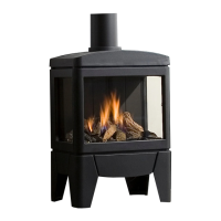
• Place the appliance at the desired place. Keep in mind that there has to be a
minimal distance of 300 millimetres between the side glass of the appliance and a
wall. At the backside there has to be a minimal distance of 70 millimetres.
• Place the flue system (see section 3.5)
• make a connection the gas connection (see
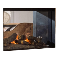
• Place the log set (see section 3.6)
• Place the glass and the cast iron front panel (see section 3.4)
• Do the functional test (see sections 4 and 5)
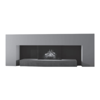
3.4 Removing of the glass
Before placing the glass: check the glass sealing rope is in good condition and makes an
effective seal. Be sure that there are no fingerprints on the glass. It is not possible to
remove those prints after you burn the appliance for a while (they are burnt in).
• Remove the cast iron frame by sliding it upwards and by tilting the downside
towards you (see figures 1.1 and 1.2)
• Hold the glass and simultaneously remove all four glass clamps (see figures 1.3 and