50
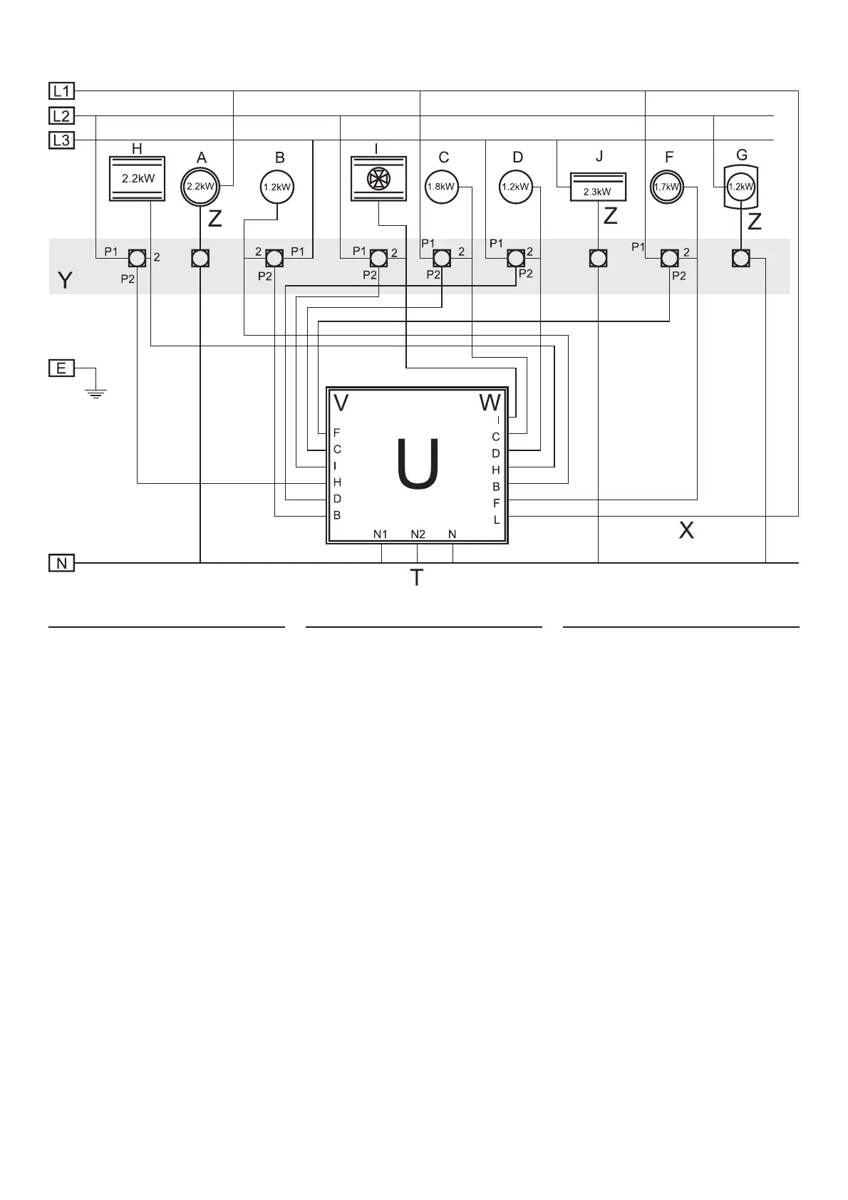
Block Diagram
Key to diagram
A Hob A
B Hob B
C Hob C
D Hob D
E Earth
F Hob F
G Hob G / Warmer
H Conventional Oven
I Fan Oven
J Grill
L Line
N Neutral
T Neutral return
U Intelligent Load Controller
V Switching Outputs
W Switching Inputs
X Live Feed From Phase 1
Y Front Panel Controls
Z Fixed Load
Blockdiagramm
Erklärung des Diagramms
A Kochfeld A
B Kochfeld B
C Kochfeld C
D Kochfeld D
E Erde
F Kochfeld F
G Kochfeld G / Warmhalteplatte
H Backofen mit Ober-/Unterhitze
I Umluftbackofen
J Grill
L Stromführend
N Nullleiter
T Rückleiter
U Intelligenter Lastregler
V Schaltausgänge
W Schalteingänge
X Spannungsführender Leiter von Phase 1
Y Bedienelemente des Bedienfelds
Z Festlast
Schéma fonctionnel
Légende
A Table de cuisson A
B Table de cuisson B
C Table de cuisson C
D Table de cuisson D
E Terre
F Table de cuisson F
G Table de cuisson / chauffe-plats
H Four conventionnel
I Four ventilé
J Gril
L Tension
N Neutre
T Retour neutre
U Contrôleur de charge intelligent
V Sorties de commutation
W Entrées de commutation
X Alimentation sous tension de Phase 1
Y Commandes de panneau avant
Z Charge fixe