40
5 Ovens
5.1 To Replace an Oven Thermostat
DISCONNECT FROM THE ELECTRICITY SUPPLY.
Remove the control panel and hotplate (see 1.1 & 2.1). Open
the oven door and remove the oven furniture.
For the right-hand oven, remove the thermostat phial cover
(2 screws). Unclip the thermostat phial from the clips in the
oven back. For the left-hand oven, pull cooker forward to gain
access to the cover box at the rear of the cooker. Remove the 4
screws securing the cover and lift clear.
Feed the thermostat capillary out of the oven. Disconnect
the wiring from the thermostat. Remove 2screws holding
thermostat to mounting panel. Fit new thermostat and
reassemble in the reverse order. Make sure that the phial is
clipped to the oven back with the phial centrally positioned
between the clips.
Check the operation of the thermostat.
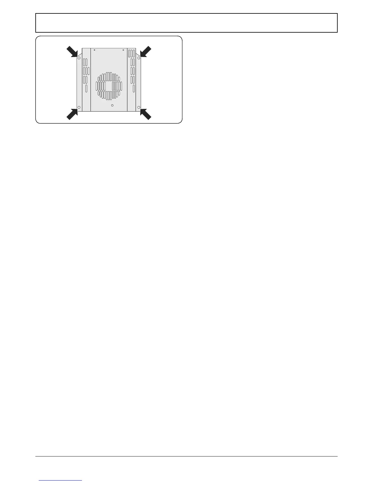
5.2 To Remove an Oven Inner Back
Open the oven door. Remove the screws and washers securing
the inner back to the back of the oven (Fig. 11.5).
Carefully lift away the inner back.
Reassemble in reverse order, making sure that you fully
tighten the 4 screws and washers.
5.3 To Change the Fan in an Oven
DISCONNECT FROM THE ELECTRICITY SUPPLY.
Pull the cooker forward to gain access to the rear. Remove
the screws securing the electric cover to the back sheet and
remove the cover. Disconnect the 3terminals connected to
the fan, noting their position.
Remove the oven inner back (see 5.2). Hold the fan blade and
remove the centre nut (left-hand thread), 2brass washers, fan
blade and circlip. Unscrew the fan retaining nuts and washers
(3 o each) and lift the fan away from the rear of the cooker.
Fit the new fan and reassemble in reverse order. Check the
operation of the oven.
5.4 To Remove an Oven Element Thermal Cut-out
DISCONNECT FROM THE ELECTRICITY SUPPLY.
Pull the cooker forwards to gain access to the cover box. Undo
the cover screws and lift clear. The cut-out is located on the
earth plate beside the oven element connections. Disconnect
the cut-out wiring. Undo the xings that secure the cut-out to
the earth plate and remove.
Fit the replacement control and re-assemble in reverse order.
Fig. 11.5