g
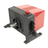
3.8 Mounting the CE protection cover on the belt drum
3.9 Connecting the LM
Disconnect power before connecting the cables.
Ensure the actuator is grounded correctly.
Observe the regulations of the electricity company
Limit the length of signal cables as much as possible. Avoid crossing low/high voltage cables.
For electrical connection of the LM refer to the following diagrams in the appendix.
• Connection LM single phase
• Connection LM three phase in star connection
• Connection LM three phase in delta connection
Connect the LM:
1. Follow all instructions on the connection diagrams.
2. Use the correct cables for the correct connections.
3. The voltage and frequency data on the actuator identification plate must correspond to the power supply.
4. Mount the cables so they cannot be damaged, and can easily be replaced in the event of a malfunction.
5. Separate low and high voltage cables by mounting them in separate cable channels.
6. If metal cable channels are used, ground them.
7. Only apply power after all the cables have been connected correctly.
3.10 Reversing the running direction
LM single phase
1. Open the lid of the reduction gear unit (reductor).
2. Change over the OPEN and CLOSE connection (terminals 3 and 4) of the limit switches.
3. Change over the connections of the inlet position feedback (terminals 2 and 4).
4. Close the lid of the reduction gear unit.
 Loading...