g
Mounting pignon on motor axle
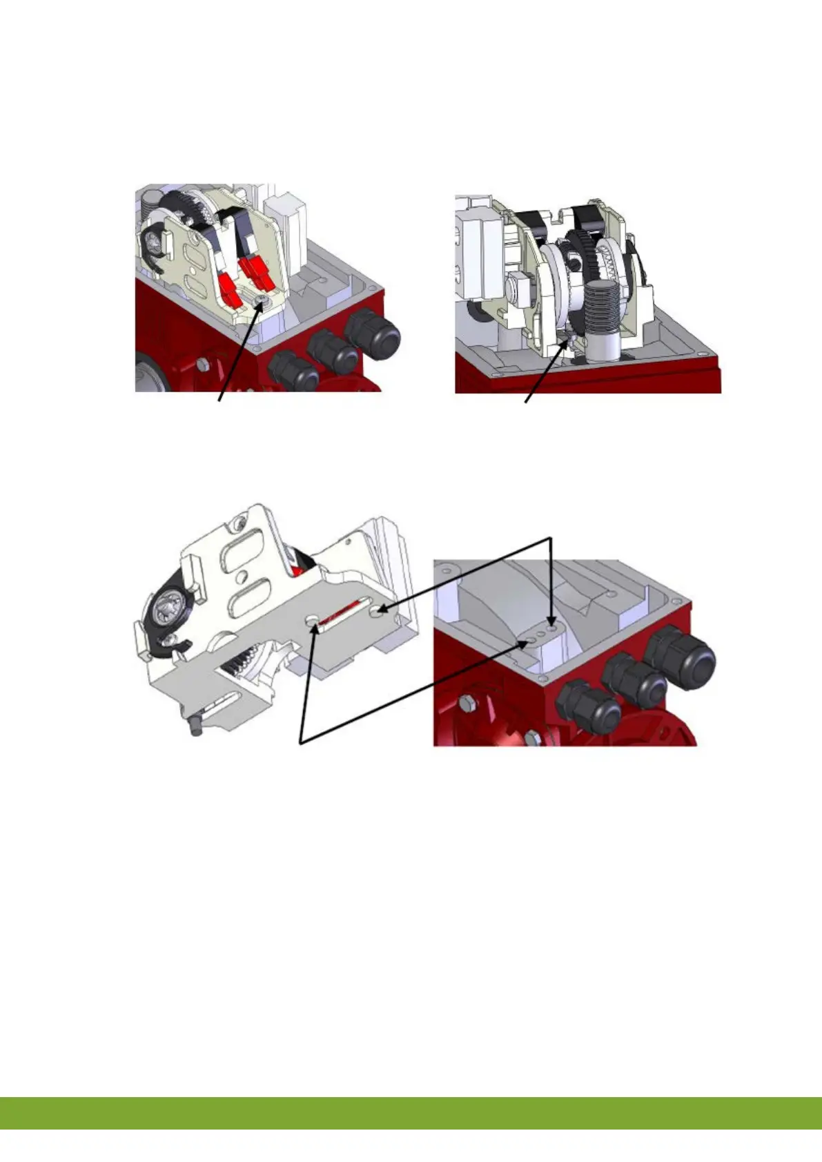
The limit switch set must be moved so the worm wheel can be mounted. Unscrew the M4 screw at the rear (~5mm).
The screw at the front does not need to be unscrewed. The limit switch set slides under the front screw head.
Screw at the rear Screw at the front
The limit switch set has alignment locks (see figure below). To move the limit switch set, lift the alignment lock out of
the opening and move it at the same time.
Position with worm wheel Position without worm wheel
Place the alignment lock in the right position and securely tighten the M4 screw. Place the worm wheel on the motor
axle and secure with the clamping bush supplied.
3.12 Testing the LM
1. Check whether the LM has been connected correctly.
2. Check whether the LM works optimally.


 To Next Page