Do you have a question about the Fancom Aura 14 and is the answer not in the manual?
Lists manuals for control computer, climate, and general operation.
Explains symbols used in the manual for tips, notes, and warnings.
Provides contact information for questions and support regarding Fancom products.
Details essential safety instructions and precautions for installing and operating the Aura 14.
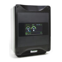
Identifies the main operational component of the Aura 14 as the touch screen.
Explains the division of Aura 14 screens into three sections: title bar, working area, and menu bar.
Allows manual setting of temperature and ventilation, temporarily overriding curve settings.
Explains how to use the left dial for temperature and the right dial for ventilation settings.
Details how the heating control prevents the section from becoming too cold.
Explains how ventilation control ensures minimum fresh air and provides extra ventilation when needed.
Explains how to set temperature and ventilation curves using bending points based on day numbers.
Describes setting temperature curves with up to 10 bending points for specific day numbers.
Details setting ventilation curves with up to 10 bending points for specific day numbers.
Shows how to request and view the alarm status and messages.
Differentiates between LOUD and SILENT alarms and how they are presented.
Lists various temperature, ventilation, and system alarms with their corresponding actions.
Explains how to handle recovered alarms, loud alarms, and silent alarms.
Describes the procedure for fully disabling the alarm system, especially when the house is empty.
Provides instructions for weekly testing of the alarm system for correct functioning.
Details how to configure absolute maximum, difference, and thermal control alarms for temperature.
Explains setting minimum temperature difference alarms and conditions for their occurrence.
Sets the time delay for alarms to prevent them during initial warm-up periods.
Describes how sensor faults are detected and indicated by an alarm.
Provides guidelines for selecting an appropriate installation location for the Aura 14, considering environmental factors.
Details the steps for physically mounting the Aura 14 unit using screw holes and a template.
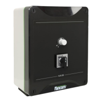
Outlines the procedure for connecting the Aura 14 to the manual switch and main supply.
Explains how to connect the Aura 14 to the FNet network, including terminal resistor usage.
Introduces the main settings applications available in the Aura 14 installation menu.
Details configuration settings like version, computer number, and temperature unit.
System settings, including system preset number, thermal control, and outside temperature influence.
Installation settings for sensor offsets and calibration values.
Analog output settings for controlling various functions like air inlets, heating, and ventilation.
Relay settings for combi-table, combi position, ventilation, and exhaust.
Natural ventilation settings, including type, waiting time, and transition speed.
Illustrates the connection diagram for the Powerboard FCA, showing sensor and relay connections.
Shows the connection diagram for the Trix board T-5, including power and fan connections.
Depicts the connection diagram for the Trix board T-10, including power and fan connections.
Illustrates the connection diagram for a single alarm unit with multiple controllers.
Shows the connection diagram for multiple alarm units integrated with controllers.
Identifies the main components of the interior control computer unit.
Identifies the main components of the Interior Control Computer T6.
Details the components and connections on the Aura board itself.
| Weight | 2.5 kg |
|---|---|
| Protection class | IP54 |
| Application | Poultry |
| Communication | Ethernet |
| Operating temperature | 0°C to 50°C |