8
fantech
DIRECT CONNECTION of both the HRV SUPPLY AIR STREAM &
EXHAUST AIR STREAM to the FURNACE COLD AIR RETURN & SUPPLY AIR SIDE
Simplified Installation
Option 2
(Supply/Return Method)
1. Furnace blower must operate when ventilation from HRV is
required. The furnace should be set to run continuously or
interlocked with HRV.
2. The exhaust air connection should be upstream of the supply
air connection to prevent exhausting any fresh air.
3. Weatherhood arrangement is for illustrative purposes only. 3m
(10') minimum separation and 460 mm (18") above grade is
recommended.
4. Due to the differences in pressure between the HRV and the
equipment it is being connected to, the HRV‘s airflow must be
balanced on site, using the procedure found section "AIRFLOW
BALANCING".
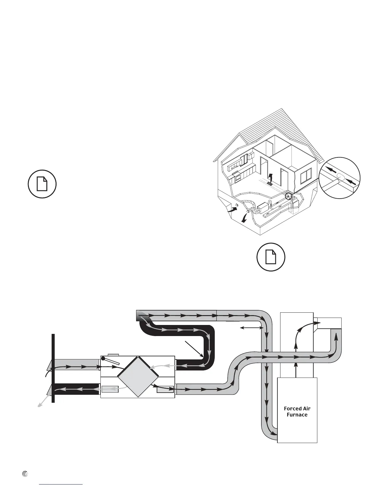
Installation examples (Cont'd)
In the case of a simplified
installation, Option 1 is
recommended.
Stale air coming from different areas of the
house (i.e. bathroom, kitchen).
* Unit air flow should be balanced while HRV is on "High" speed and fur-
nace blower is running.
Outside
Air return
1 m (3' 3")
min.
recommended
Cold air
return
* Ductwork layout may dif-
fer depending on model
HRV/Furnace ducting for Simplified Installation - Option 2
Example diagram only - Duct configuration may change depending on model