SECTION 10 -- ENGINE -- CHAPTER 1
67
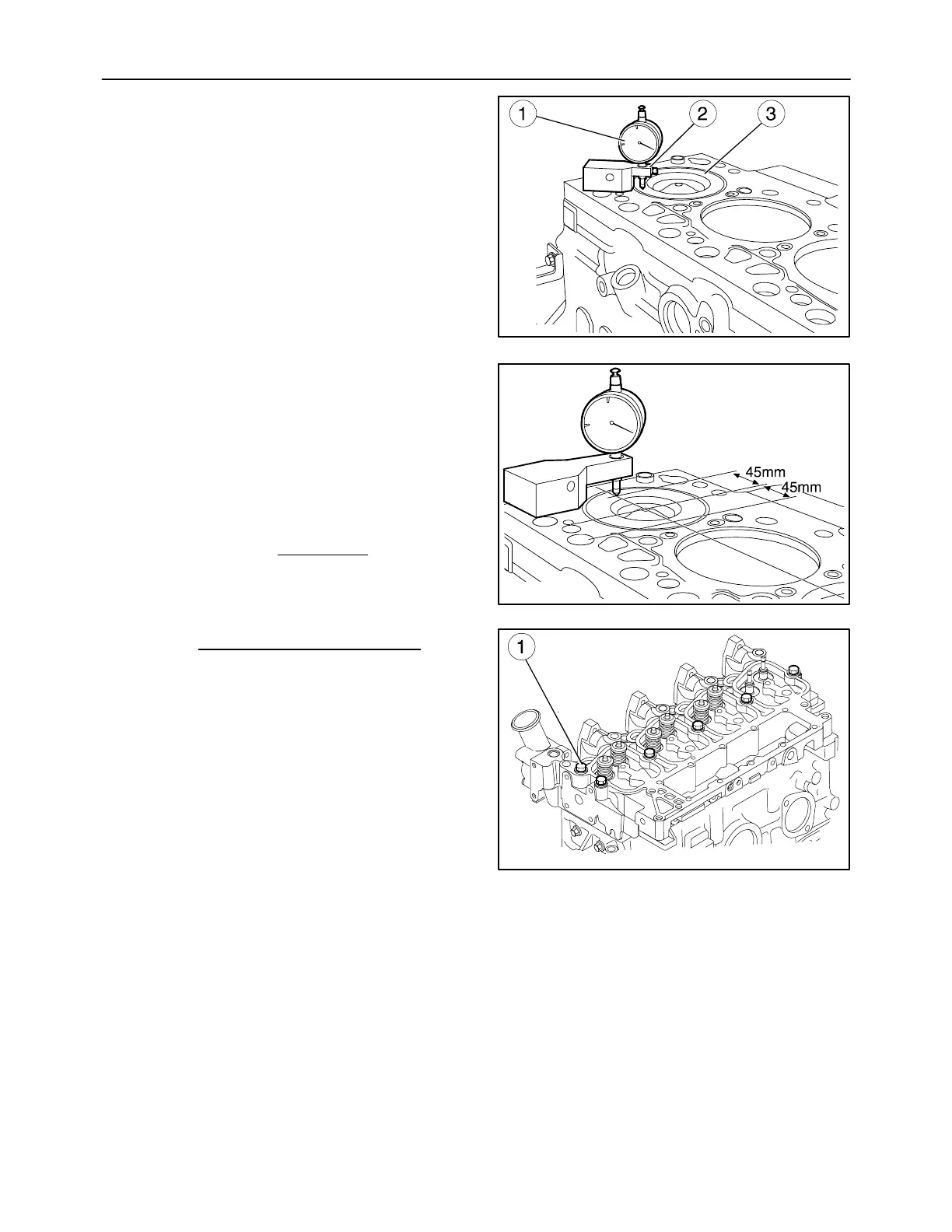
6. Using the dial gauge 380000364 (1) fitted with its
base 380000228 (2), check the protrusion of the
pistons (3) at T.D.C. from the cylinder block face is
within the tolerance limits prescribed on page 9.
MIF1080A
125
7. Since there are two type of head gasket, to choose
its thickness 1.25 mm (0.0492 in) T ype A and 1.15
mm (0.0452 in) T ype B) make the following mea-
sureme nts:
-- for each piston, as shown in the figure, at a dis-
tance of 45 mm (1.7716 in) from the center of the
piston, measure its protrusions S1 and S2 from
the top face of the crankcase and then calculate
the mean:
S1 + S2
cyl1
=
2
Repeat this operation for pistons 2, 3 and 4 and
calculate the mean value:
S
cyl1
+S
cyl2
+S
cyl3
+S
cyl4
=
4
If S is > 0.40 mm (0.0157 in) use the gasket
type A.
If S is < 0.40 mm (0.0157 in) use the gasket
type B.
8. Fit the lifting brackets to the cylinder head.
9. Install the gasket, fit the cylinder head on the
crankcase, screwing down the screws (1) with-
out tightening them to torque.
MIF1086A
126
MIF1139A
127


 To Next Page