Home
Fcar
Diagnostic Equipment
FD505
Page 41
Fcar FD505 - Page 41
73 pages
Manual
Save Page as PDF
To Next Page
To Next Page
To Previous Page
To Previous Page
Loading...
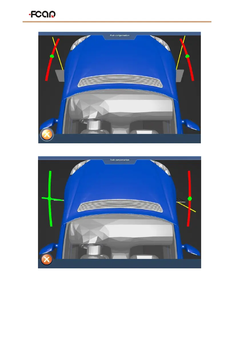
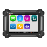
FCAR FD505 Wheel Alignment System User Manual
4
1
Figure
4.3-5 push compensation interface1
Figure
4.3-
6
push compensation interface2
6)
According
to
this
method,
the
rot
ation
is
re
versed:
left
rear
wheel,
rig
ht
rear
wheel,
right front wheel, left front wheel
;
40
42
Table of Contents
Main Page
Table of Contents
2
Contents
2
Four-Wheel Alignment System Use Precautions
4
Fcar 5D Four-Wheel Alignment System
5
Product Description
5
When Do You Need to Do Wheel Alignment
5
Definition of Wheel Alignment
6
Product Configuration
6
Product Functions and Features
9
Selection and Use of Supporting Tools
10
The Use of Corner Plate
11
Special Fixtures and Targets
11
Four-Wheel Alignment System Installation Method
12
Target Selection
13
Preparations before Wheel Alignment Operation
14
Preparation before Operation
14
Fixture/Target Installation
15
Device Connection
17
Host On/Off and Function Menu Main Interface
18
Four-Wheel Alignment System Operation Process
20
Target Monitoring
21
Ground Mode
23
Vehicle Selection
23
Vehicle Pushing Compensation
29
Caster Measurement
33
Lift Mode
37
Vehicle Adjustment
43
Data Saving
44
Maintenance Information
45
System Setting
46
Printing Information Setting
47
Target Type Setting
47
Data Unit Setting
49
Set the Front Position
49
Set Camera Parameters
50
Maintenance and Maintenance Storage Environment
51
Appendix
53
Appendix 1 Regular Procedure for Wheel Alignment
53
Appendix 2 Basic Overview of the Aligner
58
Four-Wheel Aligner Common Problems and Solutions
68
Warranty
69
Related product manuals
Fcar F7S-G
42 pages
Fcar F5 Series
40 pages
Fcar F7S series
56 pages