FCI WATERMAKERS, INC. 23Pre-I nstallation
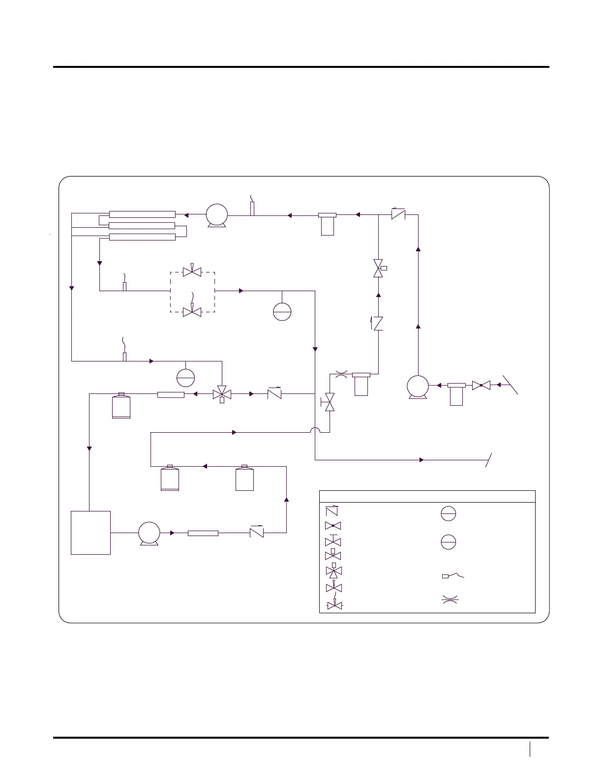
PIPING & INTERCONNECT DIAGRAM
Figure 3: Piping & Interconnect Diagram
Figure 3 shows the piping and interconnect of the components,
including standard and optional accessory congurations. Determine
the pre-ltration and post-ltration components that were supplied
with your system, and identify how each component interconnects.
Ultraviolet
(Optional)
Ultraviolet
(Optional)
Remineralization
Filter
(Optional)
Bladder Tank
(Ship’s Supply)
Charcoal Filter
(GAC, Optional)
Product
Water Tank
(Ship’s Supply)
Pump
(Ship’s Supply)
Check Valve
(Ship’s Supply)
TDS Probe
HP Transducer
FM
FM
Vessel Setup
(1, 2, or 3)
HP Pump
w/MaxQ+
w/MaxQ+APC
LP Transducer
LP Pump
Pre-Filter
Fresh Water
Flush Filter
GAC
Sea
Strainer
Sea
Water
Inlet
Brine
Discharge
Check Valve
Ball Valve
2 Way Ball Valve
2 Way Solenoid Valve
3 Way Solenoid Valve
Manual Needle Valve
Auto Needle Valve
Flow Restrictor
Flow Meter
Pressure Gauge
Legend
Particulate
Matter (PM)
Probe
FM
PI


 To Next Page