FCI WATERMAKERS, INC. 48
SYSTEM INSTALLATION / ELECTRICAL CONNECTIONS
CAUTION: DO NOT PERFORM INSTALLATION UNLESS:
1. e system feed water sea cock valve is closed.
2. e system main electrical disconnect switch is switched
“OFF,” LOCKED, and TAGGED.
WARNING: ELECTRICAL SHOCK HAZARD. A volt/ohm meter
will be necessary. e following installation procedures expose the installer
to HIGH VOLTAGE and electrical shock hazard. Only attempt this if you
are a qualied electrician and only if surrounding conditions are safe.
CAUTION: Always allow slack in electrical cables. Allow the cable to enter
or leave from the strain relief in a straight manner for several inches to ensure
proper connection, to relieve stress to the cable and tting, and to allow ease
of detachment and reattachment for maintenance or replacement. If electrical
cables are pulled tight causing them to bend at the strain relief, they will pull
out of the strain relief causing a dangerous electrical shock condition.
NOTE:
• Always follow all local and Coast Guard codes when installing this system.
• Grounding and circuit protection should be done in
accordance with National Electrical Code.
•
Ne
ver attempt to hook-up or service this system without disconnecting all power.
•
Al
ways check to make sure system voltage matches incoming voltage.
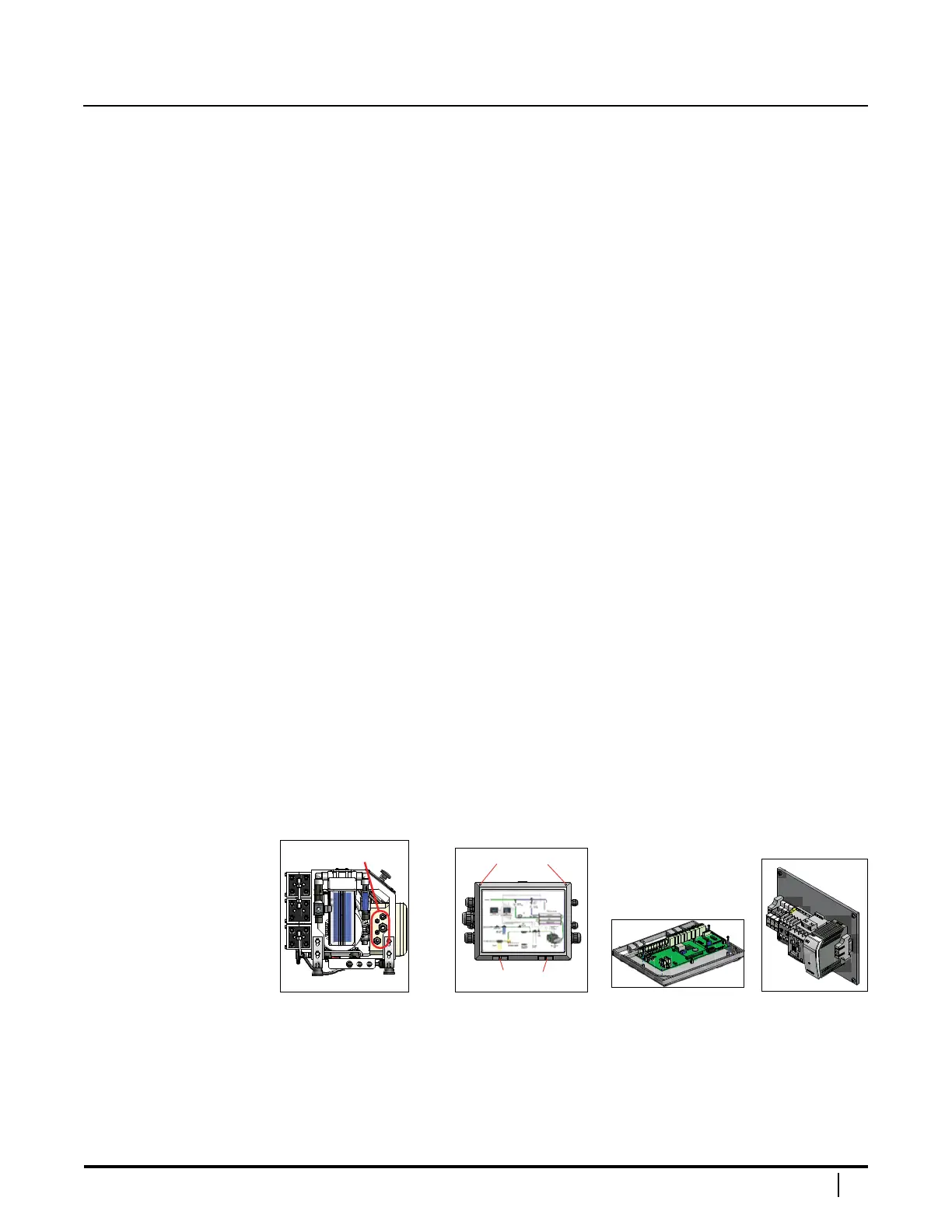
ELECTRICAL ENCLOSURE
e electrical enclosure is located behind the control panel. Cable grips are located
on the le side of the system to route the main power, the low pressure pump power,
and optional remote or inlet actuated valve wires. To open the enclosure, loosen
the two screws on the top corners of the enclosure's cover and swing door in an arc
downwards on its horizontal hinges. Opening the cover will allow access to the PC board
(attached to the back of the cover) and the contactor blocks (inside the enclosure).
System Left Panel Cover PC Board Contactor Blocks
Please refer to the wiring schematic for your unit, immediately
following these electrical connections instructions.
 Loading...