FCI WATERMAKERS, INC. 49Installation
SYSTEM INSTALLATION / ELECTRICAL CONNECTIONS (continued)
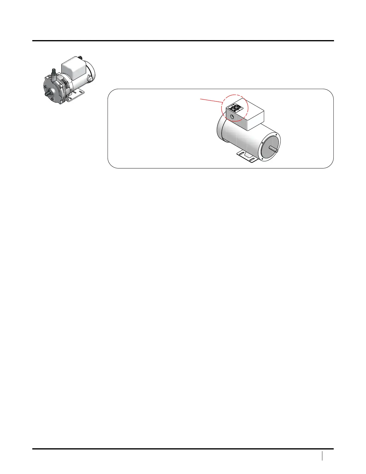
WIRING THE LOW PRESSURE PUMP
Consult local codes to determine the correct gauge wire and follow
standard color coding to attach wire the low pressure pump. Refer
to wiring diagram on capacitor cover of pump (Figure 19)
Next, feed the wires through the cable grip on the system's
le panel and into the electrical enclosure.
For single phase power, attach the wires to terminals #2T1 and #6T3 of the LPP
contactor, and #G to the green isolated ground block. See Figure 20 on page 50.
For three phase power, (50 or 60 Hz), attach the wires to terminals
#2T1, #4T2, and #6T3 of the LPP contactor, and #G to the green
isolated ground block. See Figure 21 or Figure 22 on page 51.
CAUTION: Centrifugal pumps must receive an initial prime in ALL cases.
DO NOT START PUMP BEFORE PRIMING, except to check for proper rotation
for 3-phase applications. Running with reverse rotation may cause impeller to
spin o. Merely jog switch to check rotation. DO NOT run pump with liquid
in reverse. Completely ll the pump volute and suction line. Remove air from
volute by removing top pipe plug of volute while lling. Aer lling, check
by turning pump sha a few times. Add more water if required. If pump does
not build up pressure as motor develops speed, shut down and re-prime. DO
NOT attempt to prime pump or add liquid while pump is in operation.
Wiring Diagram
on Capacitor Cover
of Low Pressure Pump
Figure 19: Wiring at the Low Pressure Pump
 Loading...