Do you have a question about the FCI 7100 SERIES and is the answer not in the manual?
It is important that this equipment be operated within its specifications.
This fire alarm control panel contains power-limited circuits.
The equipment was tested according to EC directive 89/336/EEC for Class A equipment.
The FCI 7100 is a multiprocessor-based analog/addressable fire alarm control panel.
Details standard and optional features of the 7100 Series Fire Alarm Control.
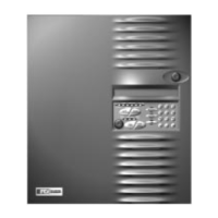
Describes the switch controls and LED indicators on the panel.
Lists and describes available optional modules like DACT, CAOM, MCOM.
Provides technical specifications for power, circuits, and connections.
Details the general steps and components for system installation.
Details AC input, battery connections, auxiliary power output, and earth ground.
Describes the system trouble and alarm dry contacts.
Explains the 24 VDC Class B, Style Y notification appliance circuits.
Describes the 24 VDC Class B, Style 4 signaling line circuits.
Details FCI approved analog sensors and address setting.
Covers FCI approved addressable modules and their address switches.
Describes addressable monitor modules for dry contacts and smoke detectors.
Details addressable output modules for controlling appliances and circuits.
Describes optional modules like CAOM, MCOM, and PTRM.
Explains the functions of the 7100-D digital communicator.
Lists UL listed receivers compatible with the 7100 for central station reporting.
Details the event reporting codes for the 7100-D DACT.
Specifies telephone line requirements and FCC compliance.
Provides information for connecting the 7100-D to the telephone network.
Warns about telephone company service changes and connection restrictions.
States FCC compliance information and required numbers.
Instructs to return the 7100-D to the factory for repair.
Lists optional accessories, including the LCD-7100 annunciator.
Describes the function of each LED indicator on the panel.
Explains the function of each switch and keypad on the control panel.
Details the selections available in the MAIN menu for system configuration.
Describes the options within the CONFIG menu: AUTO, GLOBAL, INPUTS, OUTPUTS, GROUPS, DIALER.
Explains how to perform walk tests and drills using the panel.
Covers toggling outputs ON/OFF and enabling/disabling devices.
Details how to set the system time, date, night hours, weekends, and holidays.
Describes options for displaying, printing, and clearing the event log.
Displays firmware version, configuration date, and previous menu number.
Ensures all cables and modules are installed before powering the panel.
Procedure for setting the system time and date using the keypad.
Steps to perform automatic system configuration and device initialization.
| Series | 7100 SERIES |
|---|---|
| Manufacturer | FCI |
| Sensor Type | Photoelectric |
| Operating Temperature Range | 32°F to 120°F (0°C to 49°C) |
| Type | Smoke Alarm |
| Operating Temperature | 32°F to 120°F (0°C to 49°C) |
| Alarm Sound Level | 85dB at 10 feet |
| Interconnect Capability | Yes |
| Dimensions | 2 inches |
| Humidity | 10% to 95% non-condensing |
| Humidity Range | 10% to 95% non-condensing |