FLT
®
Series FlexSwitch
TM
OPERATION
Fluid Components International LLC 19
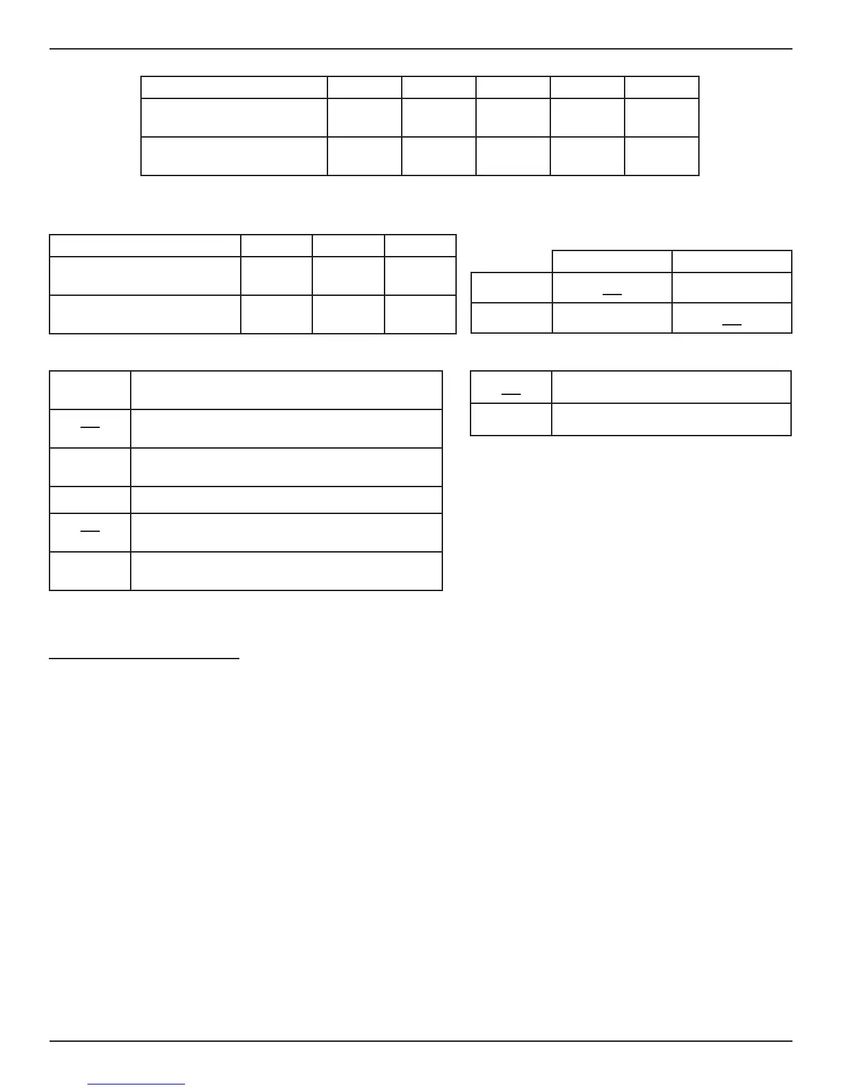
Jumper
J32 J12 J13 J14 J33
FLT93S/FLT93B Element Wattage
(110-ohm Heater)
3 watts 1.75 watts 0.75 watts* 0.21 watts OFF
FLT93F Element Wattage
(560-ohm Heater)
0.57 watts 0.52 watts 0.49 watts 0.25 watts* OFF
*J13 is standard for FLT93S/FLT93B and J14 is standard for FLT93F
Table 3-2 Selectable Heater Wattage Control
Jumper
J13 J14 J33
FLT93F Element Wattage
(560-ohm Heater)
N.A. 0.25 watts OFF
FLT93S/FLT93B Element Wattage
(110-ohm Heater)
0.75 watts N.A. OFF
Table 3-3 Fixed Heater Wattage Control (T4 Settings)
Flow/Level Temperature
Alarm No. 1
J20 J21
Alarm No. 2
J18
J19
Table 3-4 Alarm Duty/Application
Jumper Alarm No. 1
J27 Relay De-Energized With Low Flow, Low Level (Dry)
Or High Temperature
J26 Relay De-Energized With High Flow, High Level (Wet)
Or Low Temperature
Jumper Alarm No. 2
J25 Relay De-Energized With Low Flow, Low Level (Dry)
Or High Temperature
J24 Relay De-Energized With High Flow, High Level (Wet)
Or Low Temperature
Table 3-5 Relay Energization
J23 Dual SPDT (One Relay Per Alarm)
J22 Single DPDT (Disables Alarm No. 2)
Table 3-6 Alarm Qty./Relay Contact Configuration
Numerical Alarm Setpoint Adjustment
The control circuit has two mutually exclusive alarms identified as Alarm No. 1 and Alarm No. 2. Each has an alarm setpoint adjustment
potentiometer and LED indicator. Both alarms can be set up for one of three applications; flow, level/interface, or temperature. The following
application specific adjustment procedures are generic and can be used for setting either or both alarms. Use Figure 3-2 to help locate the
important setup components (potentiometers, LEDs, etc.)
Air/Gas Flow Applications
1. Remove the instrument’s enclosure cover.
2. Ensure the configuration jumpers on the control circuit are correct for this application. See Tables 3-2 through 3-6.
3. Make sure the input power is wired correctly (see Section 2).
4. Apply power to the instrument. Verify the yellow LED is on. Allow fifteen minutes for the instrument to warm-up.
5. Verify the Mode switch is in the RUN position.
6. Attach a DC voltmeter to the P1 test points with the positive (+) lead to position one (red) and the negative (-) lead to position two (blue).
7. Establish the normal process flow condition and allow the signal to stabilize.
Note:
The output signal at the P1 test points will vary inversely with changes in the process flow rate. The output signal level is
relative to the type of process media being measured and the heater wattage setting. See Figures 3-2 and 3-3.
8. Record the normal flow signal value.
Normal Flow Signal = ________ volts DC