TROUBLESHOOTING FLT
®
Series FlexSwitch
TM
40 Fluid Components International LLC
Troubleshooting the Flow Element
Use Tables 5-1 and 5-2 to determine if the flow element is wired correctly or has failed. Turn off the input power to the instrument. Unplug the
control circuit from its socket and measure the resistances below from the terminal board.
If the instrument is set up in remote configuration (flow element enclosure separate from the control circuit enclosure), and the ohm readings
are incorrect, disconnect the flow element cable at the local (flow element) enclosure. Measure the resistance as shown in Table 5-2. If the
resistances are correct then the cable between the enclosures is probably bad or not connected properly (loose, corroded, or connected to the
wrong terminals).
For normally dry conditions check for moisture on the sensing element. If a component of the process media is near its saturation temperature
it may condense on the sensing element. Place the sensing element where the process media is well above the saturation temperature of any
of the process gases.
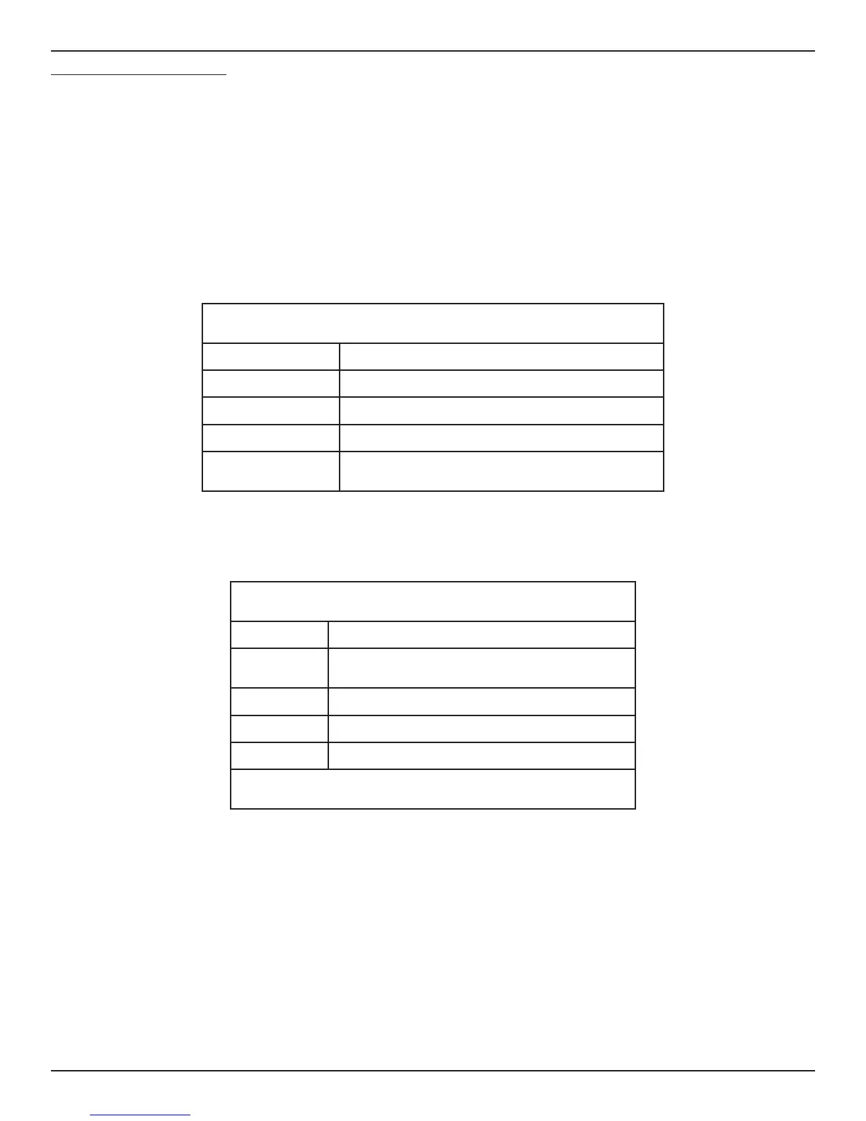
NOMINAL RESISTANCE READINGS AT THE TERMINAL BOARD
@ 78 °F PROCESS TEMPERATURE
TERMINAL NUMBER RESISTANCE
ACT TO COM 1.1 K OHMS*
ACT TO REF 2.2 K OHMS*
COM TO REF 1.1 K OHMS*
HTR+ TO HTR-
110-120 OHMS FOR FLT93S
548-620 OHMS FOR FLT93F
Table 5-1. Resistance at Control Circuit Terminal Board
(See Fig. 5-1 for test points)
NOMINAL RESISTANCE AT LOCAL ENCLOSURE TERMINAL BLOCK
TERMINAL NO. RESISTANCE
1 TO 2
110 OHMS FOR FLT93S
548-620 OHMS FOR FLT93F
3 TO 4 1.1 K OHMS*
3 TO 5 2.2 K OHMS*
4 TO 5 1.1 K OHMS*
SHIELD CONNECTED TO CONTROL CIRCUIT SOCKET ONLY. NO
CONNECTION TO LOCAL ENCLOSURE OR ITS TERMINAL BLOCK **
Table 5-2. Resistance at Flow Element enclosure Terminal Block (Remote Applications Only)
* Approximate at 78 °F (26 °C) process temperature.
** Reference wiring diagrams in the Installation section of the manual.