INPUTS / OUTPUTS
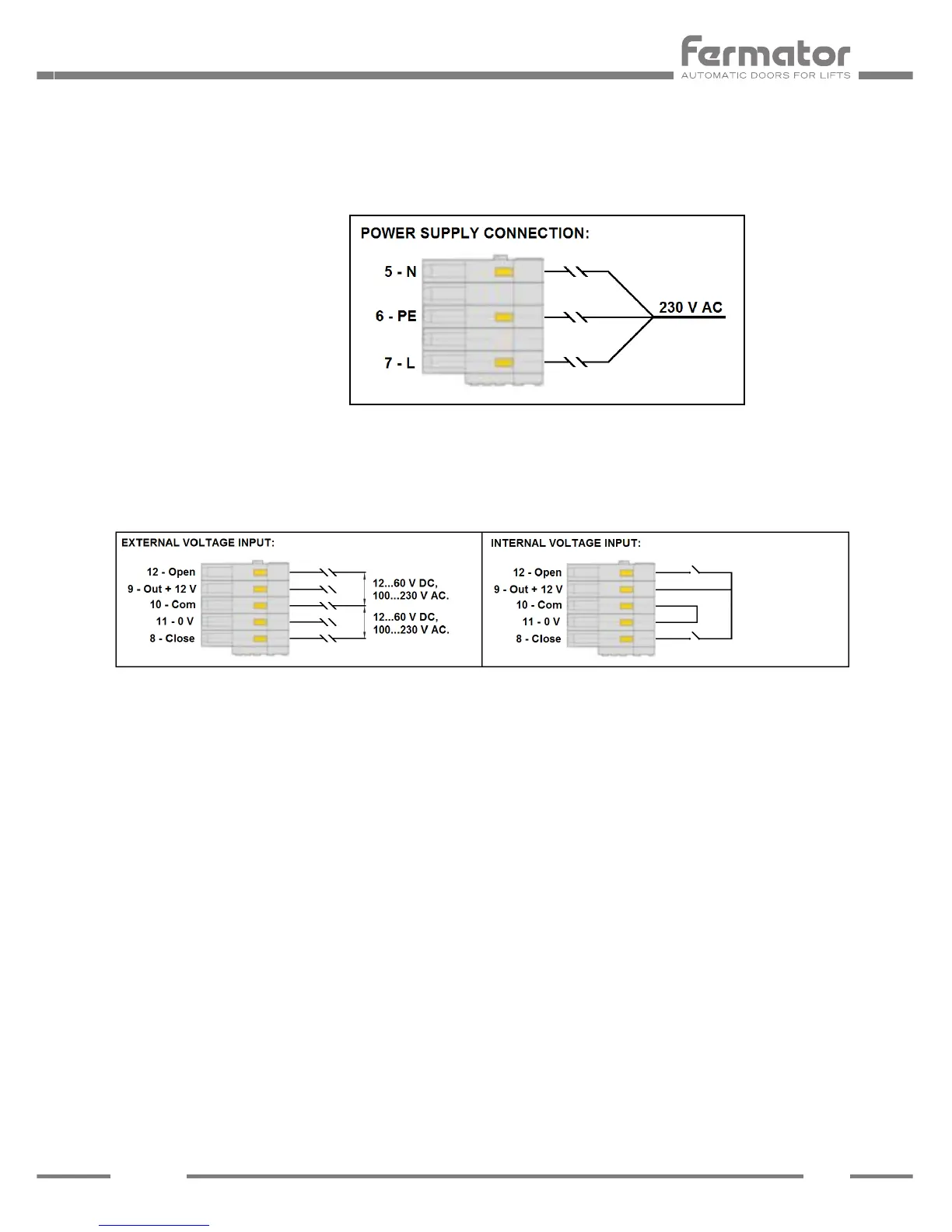
4 - 7 POWER SUPPLY.
The circuit has been designed to operate with a main supply of 230 V AC (+10%,-15%, 50
or 60 Hz).
The VF7 incorporates a soft-start system to control the bulk capacitors charge and prevent
short circuits.
Note: It is important that the Door Operator Module has a good earth connection.
INPUTS
The circuit can work with external voltage inputs or internal voltage input (voltage free contact).
8 CLOSE SIGNAL.
This signal is used for ordering to close the door. With an external voltage input the tension
to apply could be from 12 V DC to 60 V DC or 100 V AC to 230 V AC between this input and
common (10). With an internal voltage input the tension applied is 12 V DC between this input
and Out +12 V (9).
9 12 VOLT.
Isolated 12 Volts output available to control the door through a voltage free contact.
Features are:
a) This supply must only be used for this purpose.
b) This contact must be isolated from any other power supply.
10 COMMON
Is the reference used for the opening and closing signal.
11 0 VOLTS.
Is the opposite pole to 12 V, in the case of using internal voltage it should be connected
to common input.