4
© Ferno-Washington, Inc. 234-3257-01 December, 2004
Ferno Model 50-E
ILLUSTRATIONS
Safety and Instruction Labels ............................................ 6
Height and Strength Considerations.................................. 7
Stretcher Positions ........................................................... 10
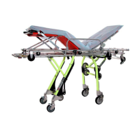
Model 50-E Stretcher Components .................................. 11
Figure 1 - Touch Bars ....................................................... 11
Figure 2 - Undercarriage Head-End Hooks .................... 12
Figure 3 - Lock Bar (Bottom of Stretcher Top) .............. 12
Figure 4 - Engaging the Quick Fix Lock ......................... 12
Figure 5 - Head-End Control Handle (Red) .................... 13
Figure 6 - Foot-End Control Handles ............................. 13
Figure 7 - Engaging a Wheel Lock ................................. 13
Figure 8 - Caster Lock Release Lever ............................. 14
Figure 9 - Locking the Swivel Caster .............................. 14
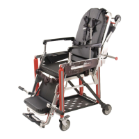
Model 155-E Stretcher Top Components ....................... 15
Stretcher Top Positions.................................................... 15
Figure 10 - Changing Stretcher Top Positions ................ 16
Figure 11 - Backrest Release Handle .............................. 16
Figure 12 - Using the Gas-Assist Backrest ..................... 16
Figure 13 - Using the Stretcher Top Side Rail ................ 17
Figure 14 - Telescoping Head-End Handles ................... 17
Figure 15 - Folding Foot-End Handles ........................... 17
Figure 16 - Chair Carrying Points ................................... 18
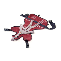
Figure 17 - Restraints Prepared for Use.......................... 19
Figure 18 - Patient Secured ............................................. 19
Figure 19 - Attaching a One-Piece Restraint
Through the Backrest .................................... 20
Figure 20 - Threading a One-Piece Restraint
Through the Seat Panel ................................. 20
Figure 21 - Positioning the Pelvis Strap.......................... 20
Figure 22 - Attaching the Pelvis Strap Bracket ............... 20
Figure 23 - Attaching a Brackrest Strap Bracket
to a Mounting Post ........................................ 21
Figure 24 - Fitting the Retaining Plug ............................. 21
Figure 25 - Adjusting Restraint Length ........................... 22
Figure 26 - Fitting the Harness ........................................ 22
Figure 27 - Adjusting the Shoulder Straps ...................... 22
Figure 28 - Patient Secured ............................................. 23
Figure 29 - Removing the Harness .................................. 23
Figure 30 - Attaching the Stretcher Top .......................... 25
Figure 31 - Stretcher Top Rollers
and Undercarriage Hooks ............................. 25
Figure 32 - Engaging the Quick Fix Lock ....................... 25
Figure 33 - Disengaging the Quick Fix Lock .................. 26
Figure 34 - Removing the Stretcher Top ......................... 26
Figure 35 - Raising the Stretcher..................................... 27
Figure 36 - Lowering the Stretcher ................................. 27
Figure 37 - Lowering by One Level ................................ 28
Figure 38 - Raising by One Level ................................... 28
Figure 39 - Placing Stretcher Top Near Patient .............. 29
Figure 40 - Placing Stretcher Near Patient ..................... 29
Figure 41 - Rolling the Stretcher ..................................... 30
Figure 42 - Increasing the Loading Height ..................... 30
Figure 43 - Preparing to Load the Stretcher .................... 31
Figure 44 - Head-End Legs Folded; Foot-End
Touch Bar in Contact with Bumper .............. 31
Figure 45 - Check That Foot-End Legs Lock ................. 32
Figure 46 - Check That Head-End Legs Lock ................ 32
Using Additional Help ..................................................... 33
Maintenance Table .......................................................... 34
Figure 47 - Tracker
™
........................................................ 35
Lubrication Diagrams ...................................................... 36
Serial Number Locations ................................................. 39