DIVAtech D LN C
27
EN
cod. 3541P710 - Rev. 00 - 10/2018
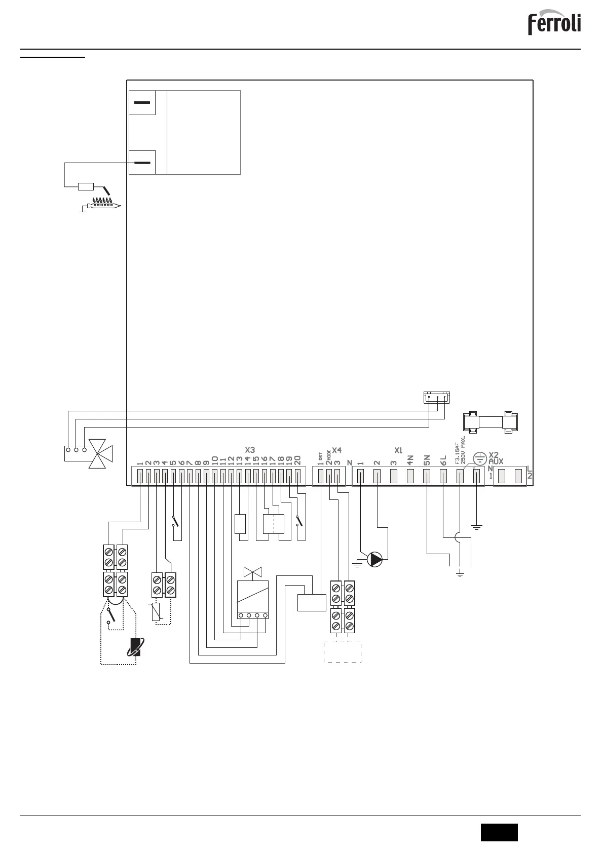
5.6 Wiring diagram
fig. 23- Wiring diagram
A
Attention: Remove the jumper on the terminal block before connecting the room thermostat or the remote timer control.
32 Heating circulating pump
42 DHW temperature sensor
44 Gas valve
72 Room thermostat (optional)
81 Ignition/detection electrode
95 Diverter valve
114 Water pressure switch
126 Fume thermostat
136 Flowmeter
138 External probe (optional)
139 Remote timer control (optional)
278 Double sensor (Safety + heating)
81
1k
W
L
N
230V
50 Hz
32
L
N
°
T
°
T
278
°
T
42
4321
44
136
ABM01A
95
321
RED
LIGHT BLUE
WHITE
GND
OUT
+5V
114 126
PWM
321
72
139
138