36
CONTROL SYSTEM
Label Description RW
Register
address
Bit
number
Lsb CPL EXP UM
Dec Hex
COOL Set point cooling RW 16900 4204 16 0 Y -1 °C
HEAT Set point heating RW 16902 4206 16 0 Y -1 °C
CF19 Remote stand by enable RW 49303 C097 8 0 Y 0 -
CF20 Remote Cooling-Heating enable RW 49304 C098 8 0 Y 0 -
CF63 Device serial address RW 49178 C01A 8 0 N 0 -
tr01 Heat pump enable RW 49665 C201 8 0 N 0 -
tr17 Heat pump lock set point RW 16930 4222 16 0 Y -1 °C
PI05 Modulating pump speed : cooling RW 49749 C255 8 0 N 0 %
PI11 Modulating pump speed : heating RW 49757 C25D 8 0 N 0 %
Hi02 Integrative electrical heaters enable RW 49858 C2C2 8 0 N 0 -
CP01 Compressor operating hours R 753 02F1 16 0 N 0 ore
PU01 Pump operating hours R 763 02FB 16 0 N 0 ore
AI01 Water inlet probe R 344 0158 16 0 Y -1 °C
AI02 Water outlet probe R 346 015A 16 0 Y -1 °C
AI03 Liquid line probe R 348 015C 16 0 Y -1 °C
AI04 Outdoor air probe R 350 015E 16 0 Y -1 °C
- Unit operating in COOLING R 33028 8104 1 4 N 0 -
- Unit operating in HEATING R 33028 8104 1 6 N 0 -
- Unit in STAND BY (user interface or serial communication) R 33028 8104 1 2 N 0 -
- Unit in STAND BY (digital input) R 33028 8104 1 3 N 0 -
- Unit in OFF R 33028 8104 1 0 N 0 -
- COOLING mode enable * W 33471 82BF 1 3 N 0 -
- HEATING mode enable * W 33471 82BF 1 4 N 0 -
- STAND BY enable * W 33471 82BF 1 5 N 0 -
- Unit switching on ( 1 = ON ; 0 = OFF ) W 33471 82BF 1 7 N 0 -
- Alarm Er05 R 33037 810D 1 5 N 0 -
- Alarm Er20 R 33039 810F 1 4 N 0 -
- Alarm Er30 R 33040 8110 1 6 N 0 -
- Alarm Er41 R 33042 8112 1 1 N 0 -
- Alarm Er45 R 33042 8112 1 5 N 0 -
- Alarm Er46 R 33042 8112 1 6 N 0 -
- Alarm Er60 R 33044 8114 1 4 N 0 -
- Alarm Er61 R 33044 8114 1 5 N 0 -
- Alarm Er62 R 33044 8114 1 6 N 0 -
- Alarm Er68 R 33045 8115 1 4 N 0 -
* If several operation modes are enabled by mistake :
- OFF has priority over STAND BY, HEATING, COOLING
- STAND BY has priority over HEATING, COOLING
- HEATING has priority over COOLING
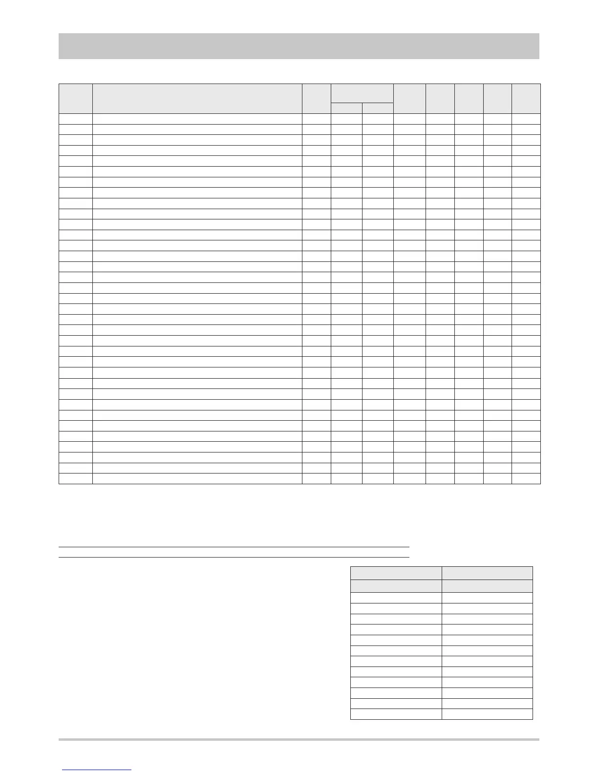
Temperature Resistance
[°C]
[kΩ]
0 25,7950
5 21,3963
10 17,7477
15 14,7213
20 12,2110
25 10,1287
30 8,4015
35 6,9688
40 5,7805
45 4,7948
50 3,9771
55 3,2989
Probes characteristics
The temperature probes used are NTC 10K (10 kΩ at 25°C).
When the probe bulb is at the temperature of 25°C the electrical resi-
stance measurable at the probe ends is 10 kΩ.
The thermistor of these probes has a negative temperature coefficient:
the electrical resistance value decreases as the temperature increases.
To find out if a temperature probe is faulty or disconnected, check the
correspondence between the resistance value in kΩ and the bulb tem-
perature in °C according to the table.
For a reliable verify it is not necessary to check all the single values but
is enough to check some random values. If the instrument indicates
neverending resistance then the probe is interrupted.
 Loading...