Troubleshooting
Application Note – Quick Start Guide for fault clearance and troubleshooting – 1.10 Seite 7 von 16
3 Troubleshooting
3.1 Error codes
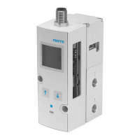
In case of malfunction of the MS6-SV check the LED display. Error codes are read by the flashing of the LED. The
error code is indicated by four flashes of the green LED (speed 2 hertz). Then the flashes of the red LED display
the error code.
Note
The number of flash pulses displays the error code.
Bouncing on the enable signals
Make sure that only debounced contacts are used
(e.g. for protective guards or doors).
Power supply is insufficient, voltage
drops, tolerance out of range
Ensure that the power supply is sufficient.
Pressure supply was interrupted
Re-establish compressed air supply
Compressed air interrupted during self-
test
Air supply on secondary side too high
(effect: pilot pressure drops)
Check compressed air supply and close actuators
(blowing air, vacuum suction nozzle)
Enable signals outside the specification
Comply with specification
(chapter 6 in this script)
Multi-pin plug socket NECA or cable is
defective
Check Multi-pin plug socket NECA or cable and re-
place if defective (chapter 7)
PLC emits test pulses that are off-set to
the enable signals (length 4 ms)
– Switch off test pulses
– Use NECA MP5 plug connector
Malfunction due to electrical or electro-
magnetic effects (EMC notes not com-
plied with)
– Comply with max. length of the signal lines
– Connect earthing correctly
– Observe min. wall distance
– Do not install cables behind the MS6-SV
– (chapter 4 in this script)
Table 1: Explanation error codes
 Loading...