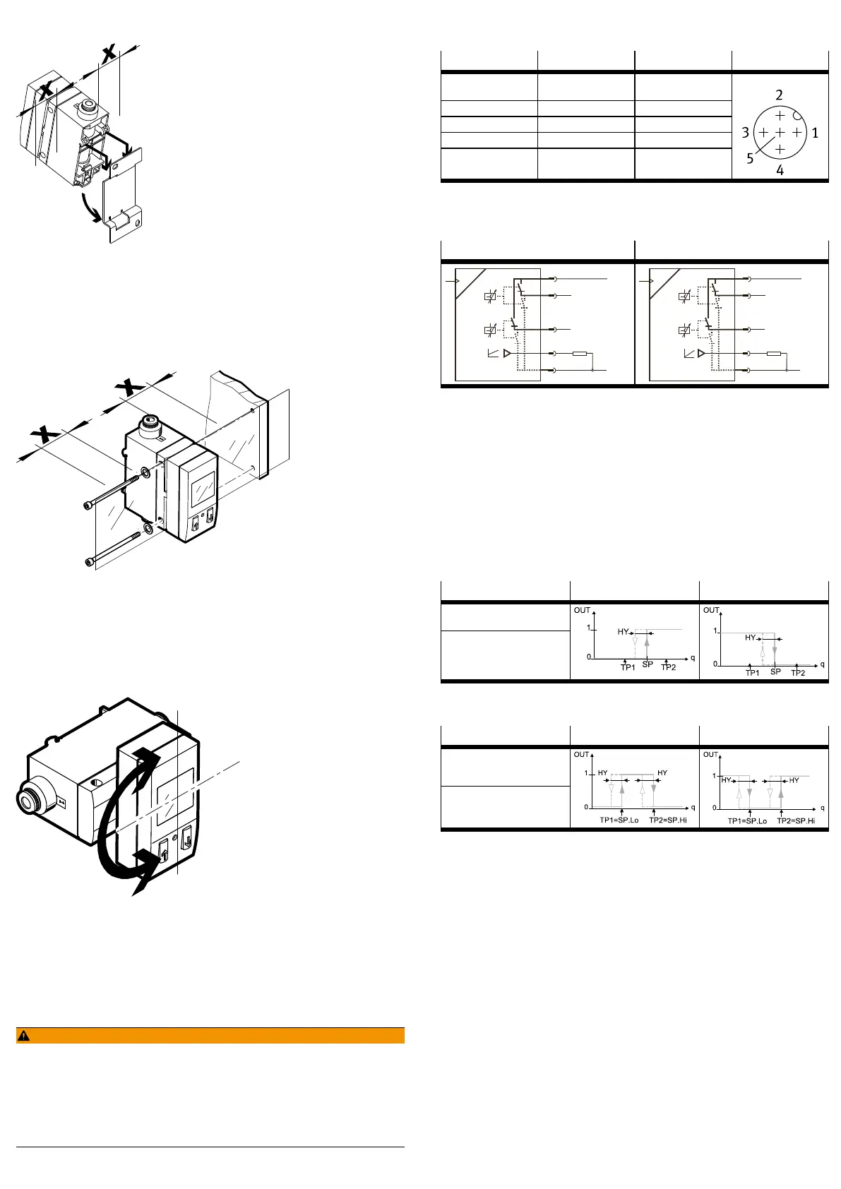
7.2 Wall mounting
Fig. 3 Wall mounting
1. Maintain lateral distance x =mm to earthed surfaces.
2. Fasten the adapter plate with 2 screws M3.
3. Hang the SFAB in the adapter plate.
4. Press SFAB in the direction of the arrow.
Ä
SFAB snaps into place.
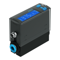
7.3 Plate mounting
Fig. 4 Plate mounting
1. Maintain lateral distance x =mm to earthed surfaces.
2. Fasten SFAB with washers and 2 screws M4.
– Tightening torque: 1Nm
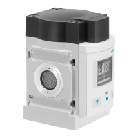
7.4 Rotate display
The display can be rotated in 90° steps. The turning range is limited to approx.
270° by a stop.
Fig. 5 Rotate display
8 Installation
8.1 Pneumatic installation
• Mount the hoses to port 1 and port 2 (flow direction èmarked on the
product).
If the tubing is incorrect, the measured values are shown flashing on the display.
8.2 Electrical installation
WARNING!
Risk of injury due to electric shock.
• For the electrical power supply, use only PELV circuits in accordance with IEC
602041/EN 602041 (Protective ExtraLow Voltage, PELV).
• Observe the general requirements of IEC 602041/EN602041 for PELV cir
cuits.
• Only use voltage sources that ensure a reliable electric separation from the
mains network in accordance with IEC 602041/EN 602041.
1. Use signal lines that are shorter than 10m.
2. Configure binary outputs according to the wiring.
– Tightening torque for the union nut at the plug connector is max. 0.5Nm
Pin Wire colour
1)
Allocation Plug
1 Brown (BN) Operating voltage
+24VDC
2 White (WH) Binary output B (OutB)
3 Blue (BU) 0V
4 Black (BK) Binary output A (OutA)
5 Grey (GY) Analogue output C
M12, 5pin
1) When using the connecting cable as per Accessories.
Tab. 1 Pin allocation
Circuit diagrams
SFAB-...-2SA SFAB-...-2SV
I
q
BN
+24 V
1
WH
BK
BU
0 V
GY
RL
PNP/NPN
4
2
5
3
q
BN
+24 V
1
WH
BK
BU
0 V
GY
RL
PNP/NPN
U
4
2
5
3
Tab. 2 Circuit diagrams
9 Commissioning
1. Switch on the operating voltage.
Ä
SFAB is in RUN mode.
2. Define the switching behaviour of the binary outputs.
– For flow measurement [FLW]: switching points [SP] and hysteresis [Hy]
– For cumulative air consumption measurement [ConS] only with OutA:
consumption switching impulse [CI]
9.1 Switching outputs
9.1.1 Switching functions
9.1.1.1 Threshold value comparator in the flow rate measurement for OutA or
OutB
Function NO (normally open) NC (normally closed)
Switching function:
– 1 switching point (SP)
TEACH mode:
– 2 teach points (TP1, TP2)
Tab. 3 Threshold value comparator
9.1.1.2 Window comparator in the flow rate measurement for OutA or OutB
Function NO (normally open) NC (normally closed)
Switching function:
– 2 switching points (SP.Lo,
SP.Hi)
TEACH mode:
1)
– 2 teach points (TP1, TP2)
– TP1 = SP.Lo, TP2 = SP.Hi
1) SP.Lo = smaller value, SP.Hi = larger value, independent of the teach sequence
Tab. 4 Window comparator
9.1.1.3 Consumption switching pulses [CI] for cumulative air consumption
measurement for OutB
A threshold value for air consumption can be set with the consumption switching
impulse [CI]. If the set threshold value is reached, a switching impulse is emitted
at the output OutA for 100ms. With each switching impulse, measurement of the
air consumption is started again.