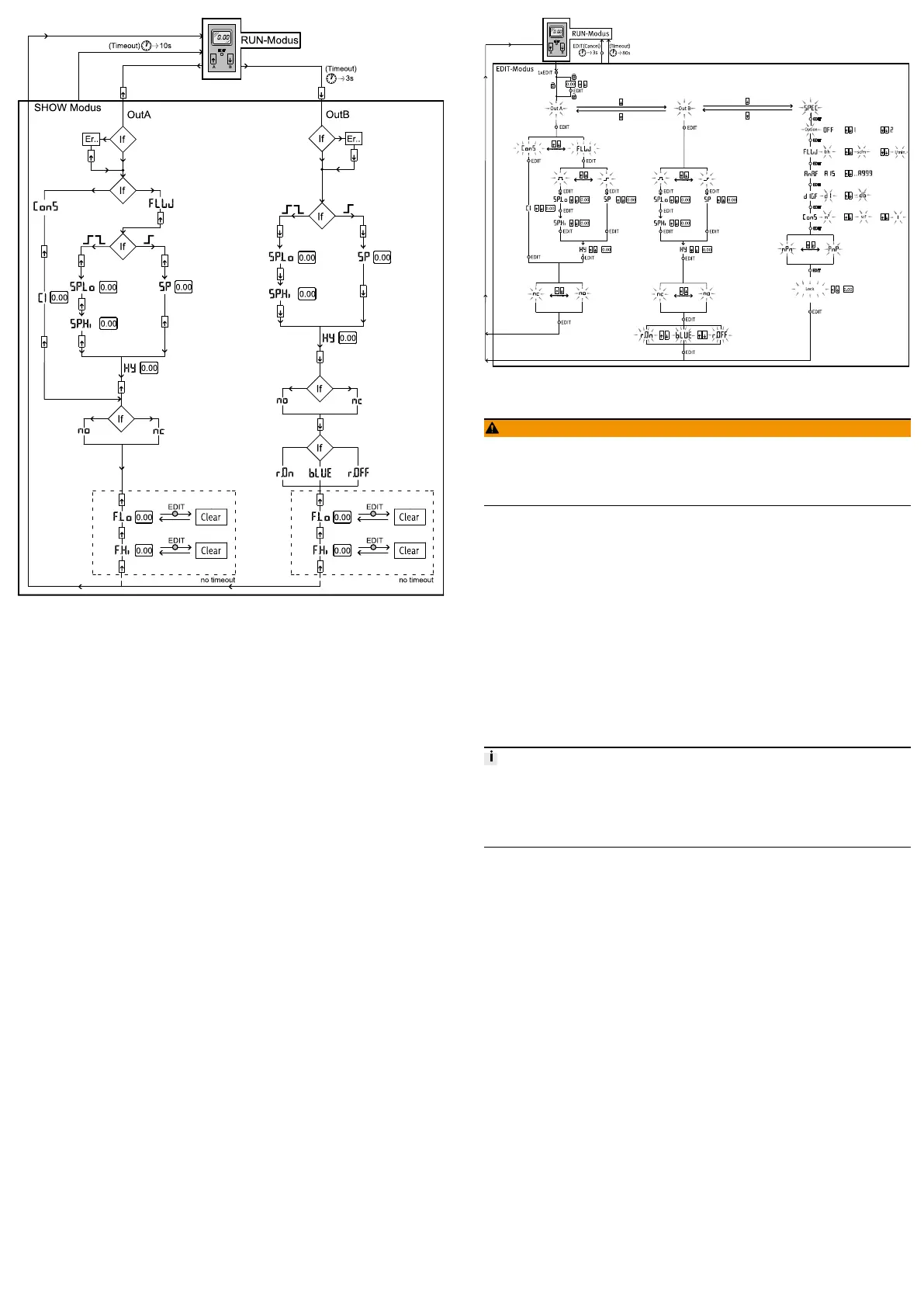
Fig. 6 Menu structure for SHOW mode
9.7 EDIT mode
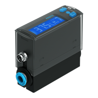
The following settings can be conducted in the EDIT mode:
– Switching mode for OutA (air consumption [ConS] or flow rate [FLW] )
– Switching function (threshold value or window comparator for OutA and
OutB)
– Switching points [SP] for OutA and OutB
– Air consumption switching impulse [CI] only for OutA in switching mode
[ConS]
– Hysteresis [Hy] for OutA and OutB
– Switching element function [no/nc] for OutA and OutB
– Colour change of the display from blue to red for flow mode (for OutB)
In addition, the following settings can be made in the special menu:
– Switching the standard conditions via [Option] (OFF, 1, 2)
– Physical units for flow rate [FLW] (l/h, scfm, l/min)
– Analogue filter [AnA.F]
– Digital filter [dIG.F]
– Physical units for air consumption [ConS] (m3, scf, l)
– Switching output [nPn/PnP]
– Security code [Lock]
Fig. 7 Menu structure, EDIT mode
9.7.1 Start EDIT mode
WARNING!
Manipulation of signal statuses may cause serious personal injury, depending
on the functioning of the machine/system.
• Note that if the switching status of the outputs is modified in EDIT mode, the
new status will be effective immediately.
The following settings can be selected with the control buttons (A/B pushbutton):
– Switching output for which the characteristics is to be set
– Special menu
1. Press the Edit button.
Ä
EDIT mode is active and [OutA] flashes. In case of active security blocking,
[Lock] flashes.
2. Press the A/B pushbuttons until the chosen security code is set.
3. Press the Edit button.
Ä
EDIT mode is active and [OutA] flashes.
9.7.2 Setting the switching characteristics of the switching outputs
Both switching outputs (OutA/OutB) can be set for flow measurement. Switching
output OutA can alternatively be set for the cumulated air consumption measure
ment. The combination of cumulative air consumption measurement (OutA) and
flow rate measurement (OutB) is possible.
9.7.2.1 Setting the switching function for flow rate measurement
The process for setting the switching outputs is fundamentally the same. Addi
tionally, the switching mode [FLW] must be selected for OutA since OutA can
also be configured for air consumption measurement. For OutB, the colour change
for the display can also be set. In the following, the process is described using the
switching output OutA.
Requirement
– SFAB is in EDIT mode and [OutA] flashes
1. Press the Edit button to confirm the selection.
Ä
[FLW] or [ConS] flashes.
2. Select flow rate measurement (FLW) with the A/B pushbuttons.
3. Press the Edit button to confirm the selection.
Ä
The currently set switching function flashes.
4. Select the desired switching function with the A/B pushbuttons.
5. Press the Edit button to confirm the selection.
Ä
[SP] or [SP.Lo] flashes.
6. Set the switching point (SP or SP.Lo) with the A/B buttons.
7. Press the Edit button to confirm the set value.
Ä
With switching function window comparator: [SP.Hi] flashes. For switch
ing function threshold value comparator: Continue with step 10.
8. Set the value (SP.Hi) with the A/B pushbuttons.
9. Press the Edit button to confirm the set value.
Ä
[Hy] flashes.
10. Set the value for the hysteresis (Hy) with the A/B pushbuttons.
11. Press the Edit button to confirm the set value.
Ä
[no] or [nc] flashes.
12. Select the switching element function (NO/NC) with the A/B pushbuttons.
13. Press the Edit button to confirm the set value.
Ä
SFAB is in RUN mode.
14. Check whether the SFAB switches as desired with a test run (vary the flow
rate).
9.7.2.2 Setting the switching function for air consumption measurement
Requirement
– SFAB is in EDIT mode and [OutA] flashes