Exercise 1 – Constructing a stepper motor system
4 © Festo Didactic GmbH & Co. KG 571861
Construction of the complete system
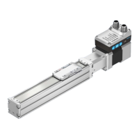
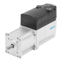
1. Connect the motor
– Make sure that the power supply is switched off.
• 24 V power supply unit is switched off
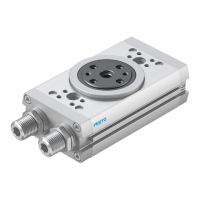
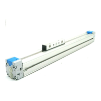
– Fasten the motor to the rotary drive using the locking screws and mount the module onto the slotted
profile plate.
– Connect the motor cable to the controller unit.
• Plug the motor cable into the socket [X6] of the controller unit and tighten it.
– Mount the proximity sensors in the sensor retainer of the rotary drive.
– Connect the proximity sensors via sensor cables to the controller unit
(D
in
6-Limit0/D
in
7-Limit1).
Note
End-position sensing can take place with sensors or using signal switches.
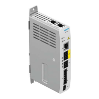
2. Connect the motor controller
– Connect the controller unit to the 24 V power supply unit using 4 mm safety plug connectors.
3. Connect the PC
– Connect the controller unit to the PC with the serial interface cable.
• Insert the sub-D plug connector of the serial cable into socket [X5] RS232/COM of the motor
controller
• Tighten the locking screws.
4. Check readiness for operation
– Make sure that the "Controller Enable" switch is switched off.
– Check all plug connectors once again.
– Switch on the power supply of the equipment. The READY LED on the front of the motor controller
should now light up.
5. Switch off system and power supply
– Switch "Power Enable", "Controller Enable", "Stop", "Start" into the position AUS/OFF
(switch upwards).