1 2
3
4 5
6 7
6160
4
Then set the routing depth to 25 mm for routing the transverse
hole. (This dimension depends on the workpiece; see dimen-
sional drawing. What is important to note is that the transverse
hole should overlap the longitudinal hole by 3 mm in depth.)
Change the routing depth to 50 mm and route the holes
(narrow hole width) in the frame according to the scribe mark
or using the stop pin system. The routing height is determined
by the material thickness, using the usual method you already
know from working with your DOMINO DF 700. In this example,
the frame has a material thickness of 30 mm. Set the routing
height to 15 mm so that the routed hole is centred in the
material.
The flip stop point, i.e. the routing height adjustment, must
always be set to 40 mm. This ensures that the transverse hole
always sits at the right distance to the edge of the workpiece
and that the anchor bolt then catches the transverse anchor.
Then route the transverse hole into the frame, where the
connector will be inserted. Flip the handle down at the front of
the edge of the workpiece and align the machine at the scribe
mark or using the stop pins (depending on how the horizontal
routed hole was set).
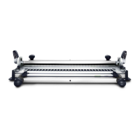
TIP For a bigger and therefore safer support surface, it is
possible and would be beneficial during this routing process
to mount the support surface extension onto the DF 700.
2016_FES_DOMINO_Book_GB-en.indb 61 03.03.16 12:13
 Loading...