Cordless reciprocating saw RSC 18
Max. pendulum stroke 3 mm
Max. material strength Wood 230 mm
Metal 20 mm
Max. cutting depth in tubes Ø 175 mm
Weight excl. battery pack 4.3 kg
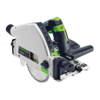
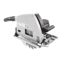
5 Parts of the device
[1-1]
Tool holder
[1-2]
Pendulum stroke switch
[1-3]
Slide switch for stroke rate control
[1-4]
Safety lock
[1-5]
Variable speed trigger
[1-6]
Rear gripping surface
[1-7]
Battery pack
[1-8]
Buttons for releasing the battery pack
[1-9]
Capacity indicator button on battery
pack
[1-10]
Capacity indicator
[1-11]
Front gripping surface
[1-12]
Saw table locking/unlocking device
[1-13]
LED lighting
[1-14]
Saw table
[1-15]
Extraction adapter
[1-16]
Scaffold hook
Accessories shown or described are not always
included in the scope of delivery.
The specified illustrations appear at the begin
ning of the Operating Instructions.
6 Battery pack
Before using the battery pack, check that the
battery interface is clean. Any contamination of
the battery interface may impair correct contact
and lead to the contacts being damaged.
A faulty contact may result in the machine over
heating or being damaged.
[2A]
Remove the battery pack.
[2B]
Insert the battery pack – until it
clicks into place.
Further information about the charger and
battery pack with capacity indicator can be
found in the corresponding operating
manual.
7 Transport and storage
CAUTION
Risk of fire due to short circuit
Risk of injury
► Transport and storage of the power tool
with ejected saw blade and disconnected
from the battery pack.
► Remove the battery pack [1-7] (see sec
tion 6).
► Remove the saw blade (see section 9.3).
► Push in the scaffold hook [1-16].
► Transport and store the power tool in a
Systainer.
8 Commissioning
8.1 Switching on/off
CAUTION! Do not press the variable speed trig
ger [1-5] until the power tool has been moved
into the working position.
► Deactivate the safety lock [1-4].
► Press the variable speed trigger = ON
Release the variable speed trigger = OFF
The LED lighting [1-13] lights up when the
variable speed trigger is pressed.
The stroke rate can be continuously adjus
ted, relative to the pressure applied to the
variable speed trigger.
9 Settings
WARNING
Risk of injury
► Activate the safety lock [1-4] and remove
the battery pack from the power tool before
performing any work on the power tool.
9.1 Electronics
Stroke rate control
You can use the variable speed trigger [1-5] to
continuously adjust the stroke rate in the stroke
rate range (see section 4). If necessary, the up
per stroke rate can be limited using a slide
switch [1-3]. This enables you to optimise the
cutting speed to suit each application.
English
17