16/68
GB
4 INSTALLATION
1
4.4 Connecting the compressor to the sources of energy and relative inspections.
4.4.1 Connecting the compressor to the electrical mains power supply
The compressor is to be connected to the electrical mains by the customer, to his
exclusive liability, employing specialised personnel and in compliance with the
Accident Prevention Norms EN 60204.
INSTRUCTIONS FOR CONNECTING TO EARTH
This compressor must be connected to earth while in use in order to safeguard the operator against
electrical shocks. The electrical connection must be carried out by a skilled engineer. It is advisable never
to dismantle the compressor or even to make any other connections. All repairs must be carried out
exclusively by authorised service centres or other qualified centres. The earth wire of the power supply
cable of the compressor must be connected only and exclusively to the PE pin of the terminal board of the
actual compressor. Before replacing the plug of the power supply cable ensure that the earth wire is
connected.
Avoid all risks of electrical shocks. Never use the compressor with damaged
electrical cables. Regularly check the electrical cables.
Never use the compressor in or near water or near a hazardous area where electrical
shocks may be encountered
ELECTRICAL CONNECTION
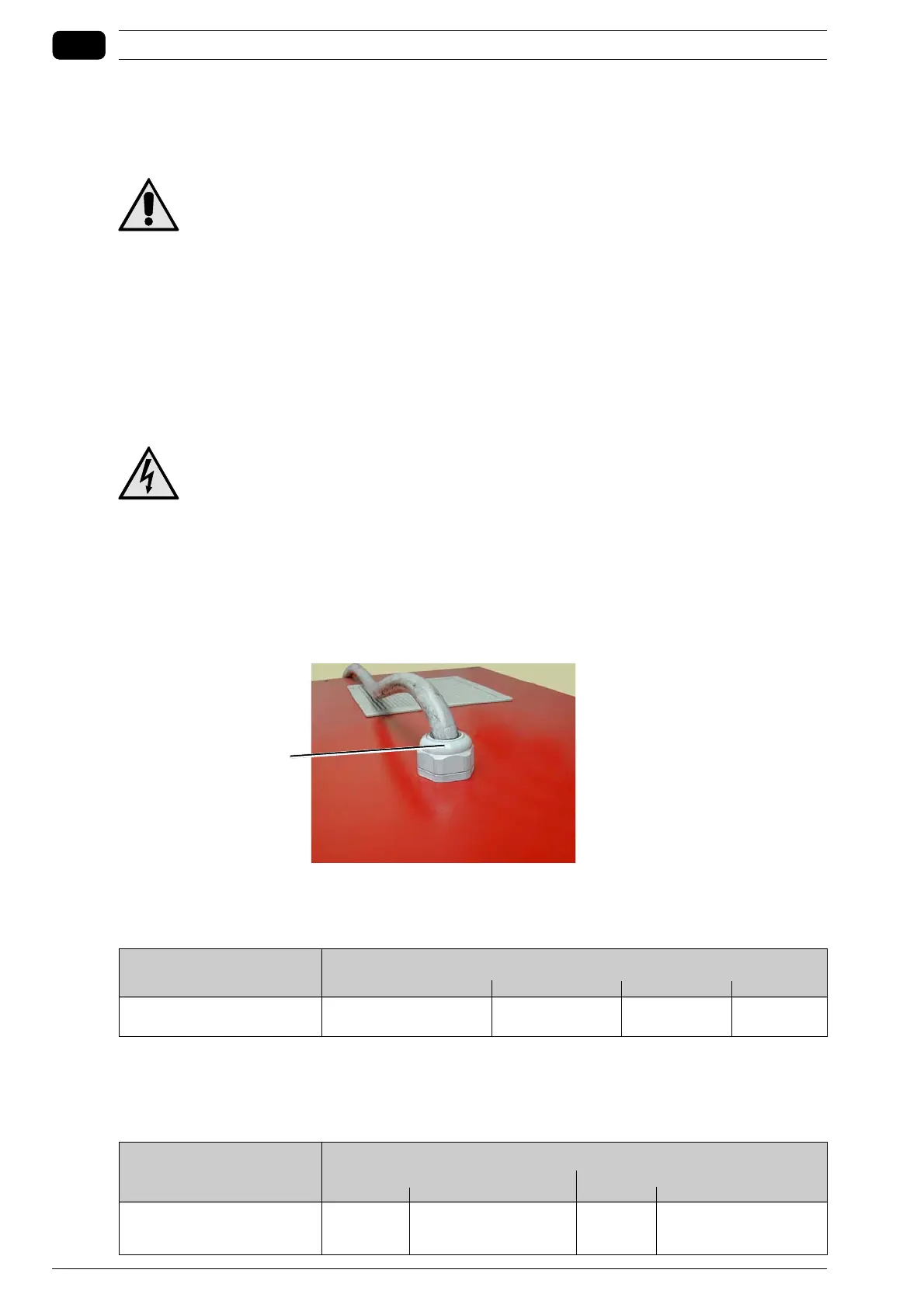
The three-phase compressors (L1+L2+L3+PE) must be installed by a qualified engineer. The three-
phase compressors are supplied without plug and cable. The power supply cable must be fed into the
electric cabinet through cable clamp 1 on the top of the electric cabinet.
Ensure that the cable cannot accidentally come into contact with moving or hot components, possibly
secure with clips. The cross section of the wires of the power supply cable (Install in open catwalks and
at maximum ambient temperature of 45°C) must be as follows:
Power Hp Rated voltage
480V 440V 380/415V 220/240V
40 25 mm
2
50 mm
2
50 25 mm
2
70 mm
2
You are recommended to install the socket and magnetothermal switch no further than 4 m from the
compressor. The required characteristics of the magnetothermal switch are given in the table that follows.
The fuses are already installed in the door locking switch and are the following type:
Power Hp Rated voltage
380/415V 220/240V
Magneto thermal switch
Fuse
Magneto thermal switch
Fuse
40 100 A 100 A 160 A 160 A
50 125 A 125 A 200 A 200 A