This document describes the Fiamma Elektra... N HE series of electric wall boilers, designed for heating-only applications. The boilers are manufactured by FIAMMA GIRO s.r.l. and comply with European directives 2006/42, IEC 60335-2-21:2012, IEC 60335-1:2010, EN 60335-2-21:2003+A1:2005+A2:2008, EN 60335-1:2012, and EN 62233:2008.
Function Description:
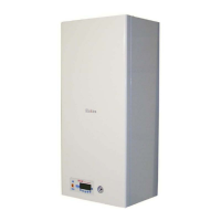
The Fiamma Elektra... N HE series are electric wall-mounted boilers designed to provide heating. They feature advanced technologies and materials to ensure maximum efficiency, total quality, and user safety. Key characteristics include noiseless operation due to maximum insulation and special materials that minimize heat loss. The boilers offer a high degree of reliability, achieved through careful material selection and rigorous testing during production. High performance and maximum efficiency are ensured by the modulation of electrical power to the heating elements, adapting to the system's actual energy needs. The D.E.S. system, with temperature probes at sensitive points, reduces power consumption when the device is not operating at maximum capacity or demand. The appliance is fully adjustable for heating system water temperature, supporting both high and low-temperature underfloor systems. Components are designed for easy front access, facilitating ordinary and extraordinary maintenance.
Important Technical Specifications:
The Elektra... N HE series offers four power levels, all sharing the same overall dimensions (Width: 400 mm, Height: 875 mm, Depth: 300 mm).
-
Elektra.6 N HE:
- Maximum electrical output: 6 kW
- Electrical supply: Single-phase 230 V - 50 Hz
- Weight: 39 kg
- Heating power: 6 kW (1 resistance group of 3x2 kW)
- Maximum pump head: 5 m H₂O
- Expansion vessel capacity: 8 liters
- Safety valve: 3 bar
- Maximum heating operating pressure: 2.5 bar
- Minimum operating pressure: 0.6 bar
- Thermal safety limit: 100 °C
-
Elektra.12 N HE:
- Maximum electrical output: 12 kW
- Electrical supply: Single-phase 230 V - 50 Hz
- Weight: 40 kg
- Heating power: 12 kW (2 resistance groups of 3x2 kW)
- Maximum pump head: 5 m H₂O
- Expansion vessel capacity: 10 liters
- Safety valve: 3 bar
- Maximum heating operating pressure: 2.5 bar
- Minimum operating pressure: 0.6 bar
- Thermal safety limit: 100 °C
-
Elektra.18 N HE:
- Maximum electrical output: 18 kW
- Electrical supply: Single-phase 230 V - 50 Hz
- Weight: 41 kg
- Heating power: 18 kW (3 resistance groups of 3x2 kW)
- Maximum pump head: 5 m H₂O
- Expansion vessel capacity: 10 liters
- Safety valve: 3 bar
- Maximum heating operating pressure: 2.5 bar
- Minimum operating pressure: 0.6 bar
- Thermal safety limit: 100 °C
-
Elektra.24 N HE:
- Maximum electrical output: 24 kW
- Electrical supply: Single-phase 230 V - 50 Hz
- Weight: 42 kg
- Heating power: 24 kW (4 resistance groups of 3x2 kW)
- Maximum pump head: 6 m H₂O
- Expansion vessel capacity: 10 liters
- Safety valve: 3 bar
- Maximum heating operating pressure: 2.5 bar
- Minimum operating pressure: 0.6 bar
- Thermal safety limit: 100 °C
Hydraulic Connections (Bottom View):
- M (Heating delivery): ¾" M
- R (Heating return): ¾" M
- VSR (Heating safety valve): ½" F (3 bar)
- RC (Manual Filling tap): Restores water pressure.
Electrical Connections:
The main electric scheme shows connections for single-phase supply (F, N), selected phase from contactor (FT), electronic pump (PI), control of contact TS on contactor of power (C-NO, cTS), control gate triacs (G1, G2, G3, G4 for 4KW or 2KW power), delivery heating probe (SM), external probe (SE), water pressure switch (PSA), safety thermostat (TS), room thermostat (TA), and general switch (ON/OFF). Triac connections are detailed, showing white, black, red, and yellow wires from the J5 plug connecting to TRIAC 2 (2 kW), TRIAC 3 (4 kW), TRIAC 4 (2 kW), and TRIAC 1 (4 kW) respectively, with corresponding black electric wires of varying sections (2.5 mmq or 4 mmq).
Manufacture Constants:
- Max Temperature Primary: 80°C
- Time of Pump Functioning in Anti-Lock: 10 sec
- Intervention Time Anti-Lock Pump: 24H
- Temperature Antifreeze ON (only circulator): 7°C
- Temperature Antifreeze ON (heat exchanger ignition): 4°C
- Temperature Antifreeze OFF: 20°C
Setpoint and Parameters (Default values):
- Heating Setpoint: 60°C (Range: 30-75°C)
- Floor Heating Setpoint: 30°C (Range: 10-40°C)
- Room Setpoint (with external probe): 20°C (Range: 10-30°C)
- External Probe Start Up: 0 (Range: 0-1)
- Building Coefficient of Dispersion: 35 (Range: 5-35°C)
- Heating Post Circulation: 30 sec (Range: 1-180 sec)
- Heating Exchanger Circulation Starting: 0 sec (Range: 0-240 sec)
- Min. Ignition Temperature Circulator: 30°C (Range: 0-50°C)
- Speed Pump PWM Operation: 4 (1=400 l/h, 2=800 l/h, 3=1000 l/h, 4=1200 l/h)
Selection Jumpers:
- JP7: High temperature / Low temperature plant (0/1)
- JP8: Combi / Only Heating (0/1)
Usage Features:
Control Panel:
The control panel, located in the lower left corner of the unit, consists of a display, function selection keys (J2, J3, J4, J5, J6, J7), a general switch, and a hydrometer.
Analogical Hydrometer:
Displays water pressure in the heating system (0-6 bar). Optimal pressure is 1-1.5 bar, with a maximum of 2 bar during temperature rise. Minimum operating pressure is 0.8 bar (+/- 0.2 bar).
Turning On the Boiler:
- Flip the light General switch (left of display) to ON. It will light up if 230V-50Hz single-phase supply is present.
- Press the ON-OFF key (J7) on the keypad to switch from stand-by to operating position. The display will light blue and show symbols for function/faults.
- Select summer or winter operation mode.
Temperature Variation of Heating Circuit:
In winter mode (snow symbol), adjust maximum heating circuit temperature using J2 (increase, III + symbol) and J3 (decrease, III - symbol) keys.
ON-OFF Key (J7):
- Puts the boiler in stand-by mode.
- Resets (unlocks) the apparatus in case of high temperature lock.
- If locked due to low water pressure, recovery is automatic once pressure is restored to 0.8 bar by opening/closing the charging tap (black handle).
Display Symbols:
- Malfunction
- Request of burner switch-on
- Heating request (III)
- Parameter menu activated
- Anti-freeze request activated
- Winter mode (snowflake)
- Summer mode (sun)
- OFF mode (circle with line)
- Level of modulation: Indicates instantaneous boiler power (0-100%).
Control of Main Heat Exchanger:
Heating elements (G1-G4) are activated fully or partially based on power demand. Each control operates for 4 seconds, with longer operation for higher power demand. Power is calculated by a PID algorithm. In simultaneous heating and tank requests, G1-G4 modulate. The order of ignition for triac G1-G4 rotates hourly to evenly distribute wear across heating elements.
Control of External Probe (Sliding Temperature):
An optional Fiamma Kit F.532 external probe can be connected to the external terminal on the general electric panel. Connection requires 1.5 mm minimum section cables, avoiding interference with electric or digital lines. After connection, parameter N°1 must be changed from 0 to 1 to enable the probe. The heating delivery setpoint (Ti) is then calculated as: Ti = [ (Troom – T e) * K e / 10 ] + Troom, where Ke is the building leakage coefficient (parameter N°2), Te is the external temperature, and Troom is the desired room temperature setpoint.
Antifreeze Function:
- If the delivery probe measures < 7°C, the circulator activates.
- If temperature drops to 4°C, the main heat exchanger ignites until delivery temperature reaches 20°C.
- Active even when the boiler is OFF (in standby mode with the general switch ON).
Heating Request:
- When the room thermostat closes, in winter mode, the system pump activates only if the primary heat exchanger temperature is higher than the setpoint (parameter N°6).
- If the primary heat exchanger probe measures a temperature lower than the programmed delivery setpoint, triacs ignite sequentially based on required power, after a delay set by parameter N°5.
- Instantaneous boiler power and G1-G4 triac control are managed by a PID regulator.
- After the request, the pump remains supplied for a time equal to parameter N°4.
- Access by pressing J3 and J5 simultaneously (symbol appears).
- J7: Exit menu.
- J2: Increase temperature index.
- J3: Decrease temperature index.
- Display shows "t :" followed by description (e.g., "Ch" for delivery, "Ep" for external, "Se" for offset setpoint), and the value.
- Access by pressing J2 and J6 simultaneously for 4 seconds (symbol appears).
- J5: Decrease parameter value.
- J6: Increase parameter value.
- J7: Exit menu.
- J2: Increase parameter index.
- J3: Decrease parameter index.
- Display shows "P :" followed by parameter index, and the value.
Degassing Function:
- Activated by pressing J4 and J7 simultaneously.
- Alters pump speed (maximum and minimum PWM) to remove air bubbles from the hydraulic circuit.
- Sequence: Vel. MAX (15 sec) -> Vel. MIN (20 sec) -> Vel. MIN (120 sec) -> Vel. MAX (5 sec) -> Vel. MIN (5 sec). This cycle repeats for 2 cycles, then 60 cycles.
- A timer on the display indicates remaining time.
Remote Control (Encrono OT1, OT2, Kronos OT11):
- Elektra N can be connected to Opentherm® compatible remote controls via an interface card and additional module.
- The remote control becomes the master, allowing direct execution of heating and hot sanitary water setpoint settings and system status control.
- Can restore the system from non-volatile lock status.
- If communication is interrupted for 1 minute, the card operates in local mode.
- Communication noise can cause error signals; if noise ends, communication is automatically restored.
- Transparent Parameters: With OT2 or OT11, 5 installer-adjustable parameters (External Probe Enabling, Building Leakage Coefficient, Heating Post Circulation, Heating Exchanger Circulation Starting, Min. Ignition Temperature Circulator) have the same meaning as described in the "parameters" table.
- Setpoint Range with Remote Control:
- High temperature system (JP7=0): 30°C ÷ 75°C (step 1°C), pre-set 60°C.
- Low temperature system (JP7=1): 15°C ÷ 40°C (step 1°C), pre-set 30°C.
- Control Panel in User Mode (with remote control):
- One/two key press activates LCD backlight.
- J5, J6, J4, J2, J3 are disabled.
- J7 unlocks safety thermostat error.
Malfunction Codes:
- Err F_X (X indicates error code)
- F 009: Hardware eeprom fault
- F 001: Insufficient water pressure in the system
- F 003: Boiler delivery probe error
- F 008: Safety thermostat lock
Maintenance Features:
The design allows for easy access to all components from the front of the unit for ordinary and extraordinary maintenance. The manual recommends contacting an authorized FIAMMA service for a planned maintenance contract to ensure optimal efficiency and safety.
Spare Parts (Examples):
- Tetrapolar Terminal block (Elektra 6/12/18, Elektra 24)
- Terminal of electric supply line (Ph, N, ground)
- General electric box (panel circuit board / contactor)
- Flat cable connection LCD display
- Left side panel of casing
- Triac of electric power (40A-600V)
- Return tube pump-boiler body
- Expansion vessel (8 lt or 10 lt)
- Water pressure switch
- Circulator at variable prevalence (electric pump)
- Flexible tube for expansion vessel
- Hydrometer
- Heating Safety valve - 3 bar
- Right side panel of casing
- Electrical wiring
- Body boiler (various models)
- Return tube (heating plant-dima)
- Outlet tube hot water heating plant-boiler body
- Lower panel (lower grid)
- PCB of operating
- Contactor of power (various models)
- O-Ring gasket for 3x2 kW electrical resistance
- Electrical resistance (3x2 kW)
- Drain tap 1/4"
- Contact safety thermostat 100℃
- Automatic bleed valve (Jolly)
- Front panel
- Display Lcd
- Instrument panel
- Lighting general switch (On-Off switch)