3 Product Installation
Caution:
1. When fitting on the fiber cover, pay special attention to the
layout of the optical fiber and make sure they are smoothly
led out of the wiring hole.
2. When the optical fiber jumper is not used, cover the
AN5506-01-A’s optical interfaces and fibers with anti-dust
caps to protect them from the dust and moisture, which
may damage the AN5506-01-A’s optical interfaces and
fiber jumpers and cause them fail to function.
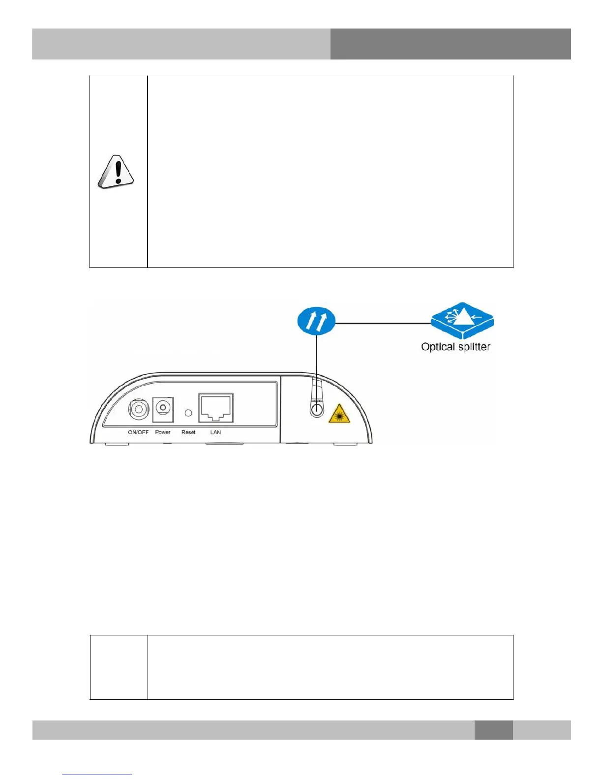
Connection diagram
Figure 3-1 Connection diagram for optical fiber
3.3.2 Connecting Network Cable
Cable and wire description
The Ethernet interface of the AN5506-01-A is connected to the user’s
PC and the switch via network cables to access data service.
Connection procedures
Step 1 Plan the layout of the network cable. Measure the distance from
the AN5506-01-A to the user terminal and choose the network
cable with an appropriate length for connection.
11
 Loading...