Installation and Operation Manual FVA-IP Camera
12 P/N 06-523 (Rev. 6) Revision Date: June, 2019
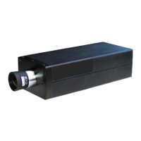
Fig5–BackplaneoftheFVA‐IPcamerashowingthelayoutoftheLED’s,anddrycontact,Ethernet,BNC,powerin,
powerout,andaudioconnections.Powerwith12‐24VDC(UL),12VDC(FM)fromULlistedClass2powersupplyfor
securityorfireshouldbeused.POEmaybeusedassupplementaltothelisted12or24voltpowersupply.
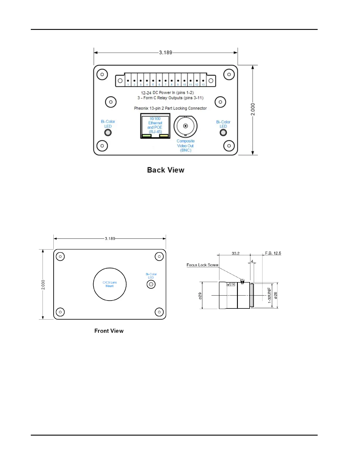
Fig6–FrontPlaneoftheFVA‐IPcamerashowinglocationoftheC/CSLensmountandFrontpanelLED.Alsothe
dimensionsofthelensareshown.
Pins 12-13 NOT used.