TWINFLEX
®
pro Repeater Panel Engineering and Commissioning Manual
13
Peripheral Bus Connections
Communications between the panel and repeater is via a multi-drop RS-485 Peripheral Bus.
2-core 1.5mm
2
screened fire resistant cable (i.e. MICC, FP200, Firetuff, Firecell, Lifeline or equivalent)
cable should be used for communications to the repeater and connected to the back board.
The maximum total
cable length from the control panel to a repeater is 500 metres.
Up to 8 repeaters can be used but they must all be within the maximum 500 metres cable length and
are wired A to A, B to B, Screen to Screen and so on up to the maximum of 8 repeaters.
The peripheral bus must be run from the panel to the first repeater then the second repeater and so on;
the peripheral bus must not be spurred from one point.
Peripheral Bus Connection Table
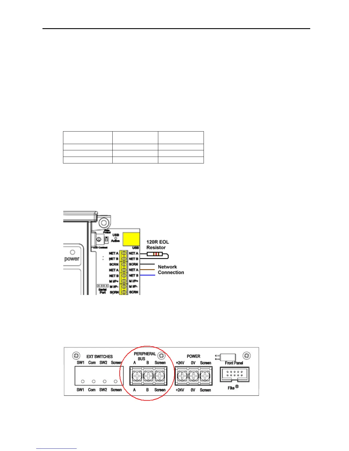
There are two sets of peripheral bus connections on the panel. These are linked in the panel so either
set can be used. A 120Ω End of Line (EOL) resistor must also be fitted across NET A & NET B at the
panel.
Example of Panel Peripheral Bus Connections Showing EOL Resistor
On the repeater a 120Ω End of Line (EOL) resistor must also be fitted across A and B but only on the
last repeater on the network.
Repeater Back Board Peripheral Bus connections