Document #50801 Rev. B 8/17/98 P/N 50801:B
27
Installation of Optional Modules with Remote Accessories
CAUTION: Remove all power (AC and DC) before installing or removing modules or wiring.
LDM-32F Lamp Driver Module
The Lamp Driver Module is used to provide an interface to a custom graphic annunciator. The LDM-32F has 32
alarm lamp/LED driver outputs which sink current to system common (-) on activation. A single positive (+) volt-
age is required to supply total operating power for all lamps or LEDs when all drivers are activated. The
LDM-32F provides a separate driver for system trouble and inputs for a local lamp test switch. A maximum of 16
external control switches may be wired to the LDM-32F. DIP switch SW3 is used to enable or disable the onboard
piezo sounder, enable remote switch functions, select a flashing LED function for new alarms and troubles and
other functions. A green ON LINE LED flashes to indicate ongoing communications with the host FACP. The
LDM-32F is supplied with four standoffs and screws for mounting to a CHS-4L chassis or custom backbox.
The LDM-32F is installed on the EIA-485 line using the LED-10IM Interface Module. Communications wiring is
supervised by the FACP. Power for the module must be power-limited.
LDM-32F Switch Settings - Use the decade rotary switches to set the address (i.e. for address '02', position
switch SW1 [top] so the arrow points to '2' and switch SW2 [bottom] so the arrow points to '0'). Refer to Table 3-
10, “Annunciator Addressing - Zone 8 Alarm LED,” on page 41
!
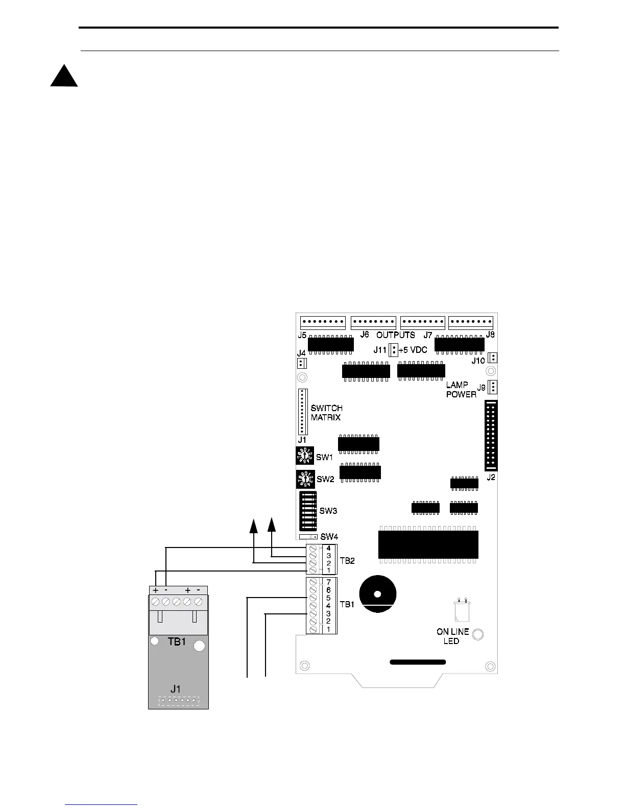
FIGURE 2-15:
Wiring LED-10IM to LDM-32F
To Next Device
EIA-485
+
-
-
+
LED-10IM
Power-limited
24 VDC Source
LDM-32F