Document 50801 Rev. B 8/17/98 P/N: 50801:B
3
CHAPTER 1: Product Description ..............................................................................................................7
1.1: Product Features..........................................................................................................................................7
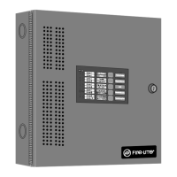
FIGURE 1-1: DP-2410BC...................................................................................................................7
FIGURE 1-2: MS-2410BC Panel ........................................................................................................8
1.2: Specifications ..............................................................................................................................................9
1.3: Controls and Indicators ...............................................................................................................................10
FIGURE 1-3: LEDs and Keypad.........................................................................................................10
1.4: Circuits........................................................................................................................................................11
1.5: Components.................................................................................................................................................11
FIGURE 1-4: Main Circuit Board .......................................................................................................11
FIGURE 1-5: MS-2410BC Cabinet.....................................................................................................12
FIGURE 1-6: Transformer Assemblies ...............................................................................................12
1.6: Optional Modules........................................................................................................................................12
1.7: Optional Accessories...................................................................................................................................12
FIGURE 1-7: BB-17F Battery Box .....................................................................................................13
FIGURE 1-8: RTB Remote Trouble Buzzer........................................................................................13
FIGURE 1-9: LED-10 Series Annunciator..........................................................................................13
FIGURE 1-10: AFM-16ATX...............................................................................................................14
FIGURE 1-11: AFM-16ATF...............................................................................................................14
FIGURE 1-12: AFM-16AF..................................................................................................................14
FIGURE 1-13: LDM-32F Module.......................................................................................................15
FIGURE 1-14: FCPS-24F....................................................................................................................15
CHAPTER 2: Installation............................................................................................................................17
2.1: Mounting Options .......................................................................................................................................17
FIGURE 2-1: MS-2410BC Mounting .................................................................................................17
2.2: Backbox Mounting......................................................................................................................................17
FIGURE 2-2: Cabinet Dimensions and Knockout Locations..............................................................18
FIGURE 2-3: FACP Backbox..............................................................................................................19
2.3: Operating Power..........................................................................................................................................20
FIGURE 2-4: Operating Power Connections.......................................................................................20
2.4: Input Circuits...............................................................................................................................................21
FIGURE 2-5: Class B Initiating Device Circuit Connections.............................................................21
2.5: Output Circuits ............................................................................................................................................22
FIGURE 2-6: Auxiliary Power Connections.......................................................................................22
FIGURE 2-7: Notification Appliance Circuit Connections.................................................................22
FIGURE 2-8: Relay Terminals............................................................................................................23
2.6: Power-limited Wiring Requirements...........................................................................................................23
FIGURE 2-9: Typical Wiring Diagram for Power-limited Requirements ..........................................23
2.7: Installation of Optional Modules with Remote Accessories.......................................................................24
FIGURE 2-10: RTB Remote Trouble Buzzer......................................................................................24
FIGURE 2-11: LED-10IM Installation................................................................................................25
FIGURE 2-12: Wiring LED-10IM to LED-10 Series .........................................................................25
FIGURE 2-13: ABS-8RF.....................................................................................................................26
FIGURE 2-14: Wiring LED-10IM to ACM-8RF................................................................................26
FIGURE 2-15: Wiring LED-10IM to LDM-32F.................................................................................27
FIGURE 2-16: Wiring LED-10IM to AFM-16ATX...........................................................................28
FIGURE 2-17: 4XTMF Module Connections.....................................................................................29
CHAPTER 3: Programming Instructions.....................................................................................................30
3.1: Switch Functions.........................................................................................................................................30
FIGURE 3-1: Programming Mode Keypad.........................................................................................30
3.2: Programmable Features and Options ..........................................................................................................31
TABLE 3-1: Programming Features and Options ...............................................................................31
Table of Contents