6
15
6.4 INSTALLATION - SEALED SYSTEM HEATING CIRCUIT
(b) Static head may be higher than calculated. In
this case it is necessary to re-measure static
head and revise expansion vessel air charge
pressure.
(C) Expansion vessel incorrect size or air charge
pressure incorrect.
Refer to BS 7074
Part 1 and BS 5449 for further information.
Nearest available stock size for additional vessel
required, at 1 bar initial system pressure (taken from
above table) is 5 Litres.
It is emphasised that the installer should be fully
acquainted with sealed system installation and
operation, calculation of total system water volume,
determining of initial system pressure required and
calculation of any additional expansion vessel volume
required. Warranty is void when the boiler is
installed in a system with insufficient expansions.
NB. Ensue that all expansion vessels in the same
system are set at EQUAL air charge pressures.
SYSTEM FILLING, TESTING AND MAKE-UP
Introduction
Mains cold water is supplied through the boiler
drain/fill valve.
Heating Circuit
This is the radiator heating system including the boiler
which is filled from the mains supply via a flex filling
loop to a pressure determined from the system static
head, expansion vessel size and system water volume.
This flexible filling loop should be disconnected when
boiler and system are filled and checked (see method
B).
System filling should take place slowly and can
be completed via the following method:
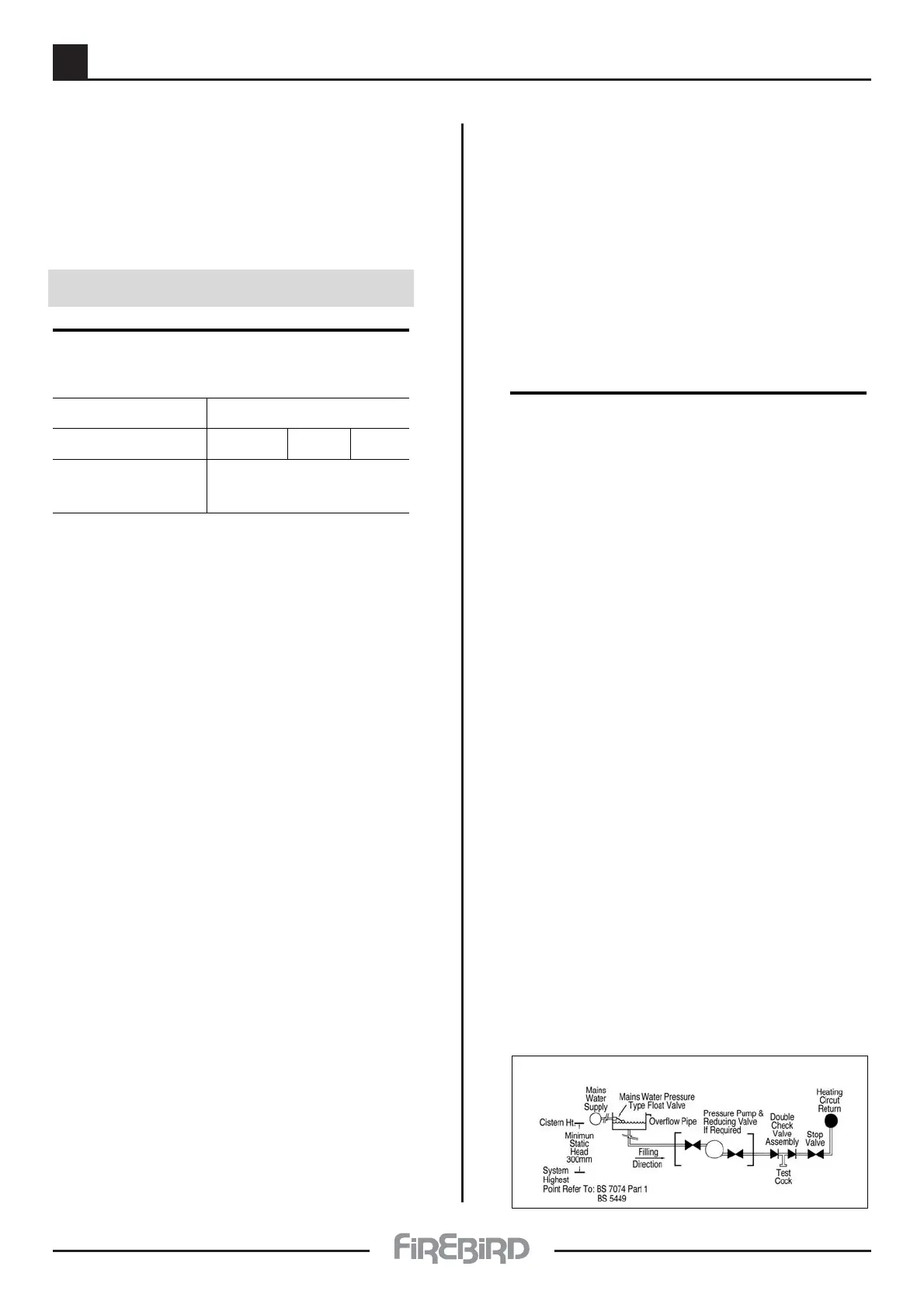
Automatic Filling
Automatic System filling may be made with a feed and
make-up cistern connected through a double check
valve and stop valve assembly to the return side of the
heating system as close to the boiler as is practical.This
cistern should be located above the heating systems
highest point to give a minimum static head of 300 mm
between it (highest point) and cistern. The manual
filling system fitted to boiler should then be
disconnected and connection points blanked off.
This system has the advantage of automatic water
make-up in the event of system pressure loss due to air
elimination and minor leaks. In any case control panel
pressure gauge should be occasionally checked.
Safety Valve Setting 3 bar
Initial System Pressure 0.5 bar 1.0 bar 1.5 bar
Total Water Content TOTAL VESSEL
of System VOLUME **
Litres Litres Litres Litres
25 2.1 2.7 3.9
50 4.2 5.4 7.8
75 6.3 8.2 11.7
100 8.3 10.9 15.6
125 10.4 13.6 19.5
150 12.5 ->[16.3]<- 23.4
175 14.7 19.1 27.2
200 16.7 21.8 31.2
225 18.7 24.5 35.1
250 20.8 27.2 39.0
FOR FURTHER INFORMATION CONSULT
APPROPRIATE TRAINING MANUALS
AND BS 7074 PART 1, BS 5449, ETC
* * When calculating size of any additional
expansion vessel required, remember to deduct
the boiler expansion vessel volume of 12 litres
from the calculated total system vessel volume
required, as given in above table.
EXAMPLE: using above table
If total water content of system is - 150 litres
and initial system pressure required is - 1.0 bar
then vessel volume required is - 16.3 litres
[from above table]
The vessel supplied with boiler is - 12.0 litres
therefore an additional vessel of - 4.3 litres
is required
(minimum)
(For this system of 150 litres - total water volume)
EXPANSION VESSEL AND SYSTEM
REQUIREMENTS
METHOD B
 Loading...