6
14
6.4 INSTALLATION - SEALED SYSTEM HEATING CIRCUIT
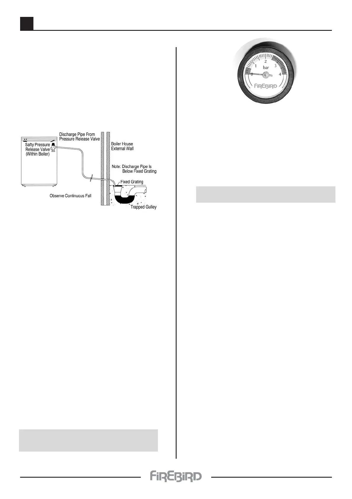
When the system is cold and filled to initial fill pressure
P
i
the pointer on the pressure gauge should point at 1
bar.
The pressure gauge shown has two red zones marked
on it. The first is between 0 and
1
/2 a Bar. If the pointer
falls into this zone when system and boiler are cold this
is indicating that initial System Fill Pressure has
dropped and this will activate the pressure switch
cutting off power supply to the Combi C. Refill system
manually until indicated pressure rises to 1 bar.
N.B. Insufficient pressure in the boiler will cause
power supply to switch off.
* A 12 litre expansion vessel is fitted to boiler,
precharged with air or nitrogen to 1 bar which allows
a system static head of 5 metres. If the static head is
greater than this then the air charge in the vessel must
be increased to balance the higher static head. The air
charge should not exceed a pressure of 1.5 bar.
If static head is altered then it is also necessary to alter
air charge pressure to equal static head (+ 0.3 Bar).This
is necessary in order to keep system water from
entering expansion vessel until system is being heated
and thus allow its maximum acceptance volume (V) to
be used only to accommodate the expansion of
system water during boiler operation.
Remember that air charge pressure must be equal in
both vessels (attached to the same system). In the
above example this is 1 bar. Air charge pressure is the
air pressure in expansion vessel before system is filled.
It is measured with a tyre gauge attached to Schrader
valve on the vessel.
N.B. The second red zone is between 2
1
/2 and 4 bar
pressure. When the heating system is up to full
working temperature, if the pointer on the
pressure gauge should enter this red zone
showing a final system design pressure of more
than 2
1
/2 bar, it is likely that:
(a) Total system water content is greater than
that calculated and if additional expansion
vessel has been fitted it should be replaced
with a larger unit
OR if integral boiler expansion vessel only is
used then an additional expansion vessel is
required.
SEALED HEATING CIRCUIT
The system must comply with BS 7074 Part 1 and BS
5449 Part 1 with a maximum water temperature of
80˚C.
* A manual reset overheat limit thermostat is located
at the rear of the electrical control panel. If a boiler
overheat condition arises the burner will stop and
remain inoperative until this thermostat reset
button is depressed.
* A pressure relief valve to BS 6759 operating at 3 bar
(45 lb/in
2
) is fitted. A discharge pipe of 15 mm
diameter is also fitted to the discharge connection
on the pressure relief valve. During installation an
extension pipe should be fitted to this, leading, to
outside the building.The pipe should be as short as
possible and may need a tundish fitted in a
protected position within the building.
Note:- Water must not discharge above an
entrance, window or where public have access.
The installer must be aware that the discharge
may be boiling water.
* A drain valve must be fitted at the lowest points in
the system to enable draining as necessary. A drain
valve is already fitted at the bottom of the boiler to
enable draining of boiler and tank unit only. All
pipes connected to boiler should have shut off
valves fitted to facilitate this.
* A Pressure gauge, having range 0 to 4 bar is fitted to
boiler control panel.This indicates water pressure in
boiler and system at time of reading. Pressure
when cold should be
1
/
2
bar minimum to 1.5 bar
maximum. This is known as Initial System Design
Pressure (P
i
).
N.B. Initial System Design Pressure (measured in
bar) equals static head of system (measured in bar)
plus 0.3.