EasyManuals Logo

FireBird Enviromax Systems C20 User Manual

FireBird Enviromax Systems C20
52 pages
To Next Page IconTo Next Page
To Previous Page IconTo Previous Page
Page #36 background imageLoading...
Page #36 background image
9
34
9.1 BURNER - SETTINGS
Smoke
Bacharach
0-1
0-1
0-1
0-1
0-1
0-1
0-1
0-1
0-1
0-1
0-1
0-1
0-1
0-1
0-1
0-1
CO
2
11.5%
11.5%
11.5%
11.5%
11.5%
11.5%
11.5%
11.5%
11.5%
11.5%
11.5%
11.5%
11.5%
11.5%
11.5%
11.5%
Avg.
Fg. ˚C
70
70
75
85
90
95
60
65
70
70
75
80
70
80
80
80
Air
Box
1
1
1
2
2
2
2
2
2
-
-
-
-
-
-
-
Comb
Head
-
-
-
-
-
-
-
-
-
1.0
1.5
2.0
3.0
5.0
5.0
5.0
Pump
Pressure
12 bar
13 bar
12 bar
12 bar
12.5 bar
13.5 bar
12.5 bar
14.0 bar
12.0 bar
12 bar
14 bar
12 bar
13 bar
12.0 bar
14 bar
12.5 bar
Blast
Tube
T3
T3
T3
T5
T5
T5
T5
T5
T5
Adj.
Adj.
Adj.
Adj.
Adj.
Adj.
Adj.
Air
Shutter
3.2
3.5
4.5
2.2
2.8
4.0
4.5
6.0
6.5
4.5
6.5
5.5
5.8
7.5
7.5
8.0
Nozzle
Size - Angle - Type
0.50 80˚ S
0.50 80˚ S
0.55 80˚ S
0.55 80˚ S
0.65 80˚ S
0.65 80˚ S
0.85 80˚ S
0.85 80˚ S
1.00 60˚ S
1.10 60˚ S
1.10 60˚ S
1.25 60˚ S
1.35 60˚ S
1.50 60˚ S
1.75 60˚ S
2.00 60˚ S
RDB 2.2R
RDB 4.2R
Burner
C 26
C 35C 44C 58
Model
C 100
Output
kW BTU
22 75K
23 80K
26 90K
26 90K
31 110K
35 120K
40 135K
42 145K
44 150K
54 150K
56 174K
58 198K
68 232K
73 249K
90 272K
100 340K
Restrictor
Disc
-
-
-
-
-
-
-
-
-
-
-
-
-
-
-
-
Deflector
Plate
STD
STD
STD
STD
STD
STD
STD
STD
STD
-
-
-
C100
C100
C100
C100
C 73
RDB T1 RDB T5RDB T3
Dia. 18mm
To p
Hole to aid
photocell
Clearance for
electrodes
4mm
holes
Dia. 20mm
To p
Hole to aid
photocell
light detection
Clearance for
electrodes
Dia. 23mm
To p
Hole to aid
photocell
light detection
Clearance for
electrodes
Air Box 1
Air Box 2
T1 Part No. 7137
T5 Part No. 7140
T3 Part No. 7139
Riello RDB 2.2 Range Burner Settings
Variations in nozzle throughput, flue type & draught, oil viscosity etc. may give results differing from these
laboratory performance figures. These settings were carried out using a conventional flue.
DIESEL SETTINGS FOR FIREBIRD BOILER RANGE USING RDB 2.2 & 4.2 BURNERS
The burner nozzle, pump pressure and air setting may have to be changed from the factory setting to suite site conditions.
The above settings were carried out on a Firebird condensing boiler with 2 metres of vertical balanced flue.The ambient air was
averaging around 20˚C. Allowances should also be made for the viscosity of the oil and the tolerance of the nozzles.
These settings are a guide and should only be used as such. A flue gas analyser must be used when fine tuning a burner to a boiler.
When using this chart on a burner fitted to a standard efficient boiler air setting may vary.
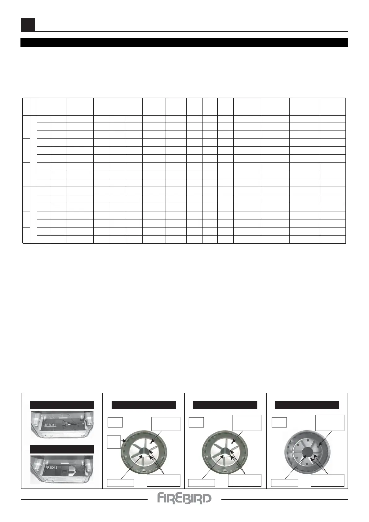
Steps in commissioning a Firebird boiler burner:
1. Check nozzle to required output.
2. Is the correct burner head fitted to the burner for the required output?
3. Set air damper using the guide above to the desired output.
4. Check the pump pressure.
5. Set boiler thermostat to minimum and allow boiler to heat up before carrying out a flue gas analysis.
6. Check flue gasses with a smoke gun before using flue gas analyser.
7. Proceed with flue gas analysis, adjust air damper to get desired CO
2
%.
8. Print a record of analysis result.

Questions and Answers:

Question and Answer IconNeed help?

Do you have a question about the FireBird Enviromax Systems C20 and is the answer not in the manual?

FireBird Enviromax Systems C20 Specifications

General IconGeneral
BrandFireBird
ModelEnviromax Systems C20
CategoryBoiler
LanguageEnglish

Related product manuals