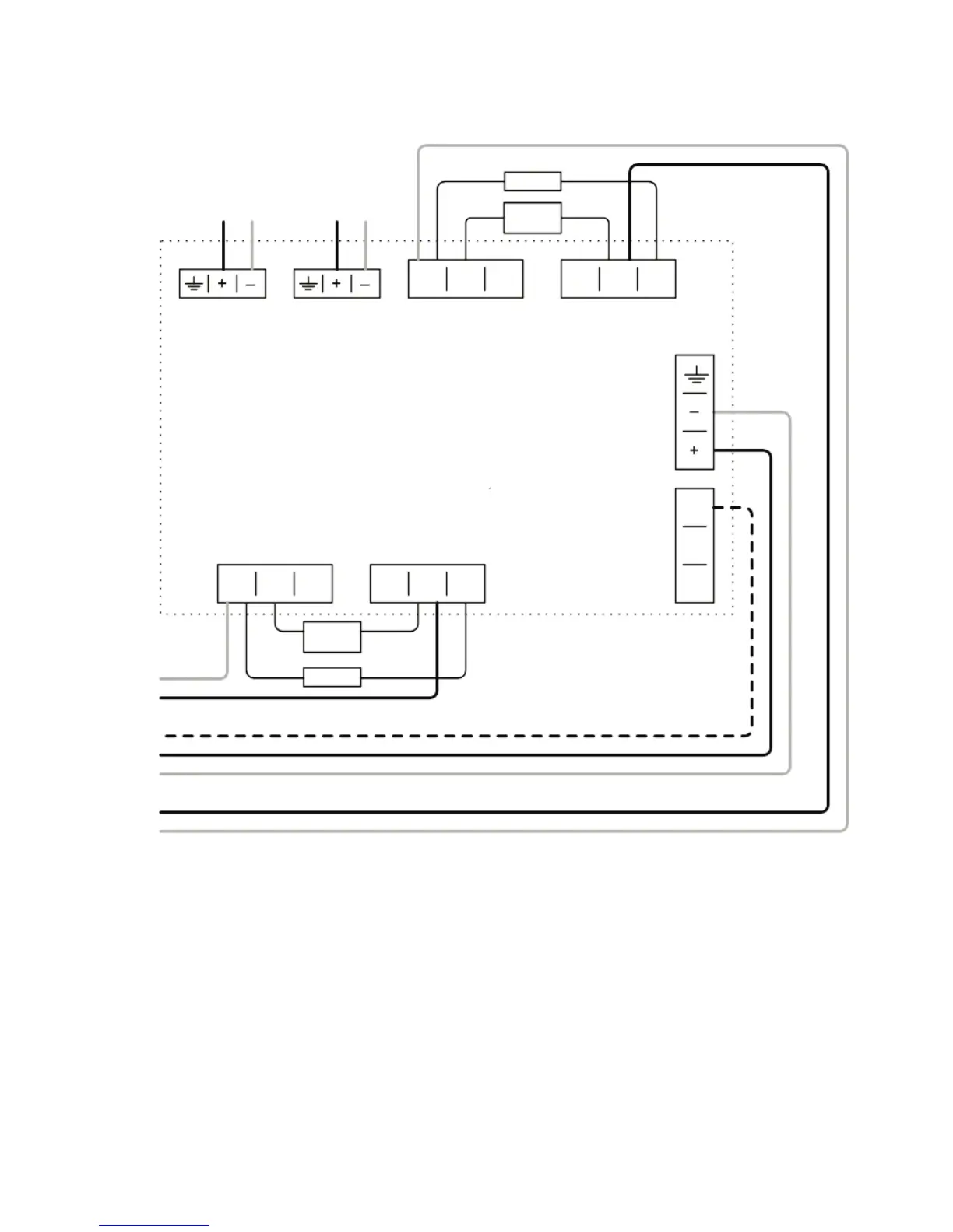
3. Wiring Diagrams
4
Wiring two Detectors onto two Zones:
To Detector 1 To Detector 2
EOL
EOL
DET 1 DET 2
N/O COM N/C N/O COM N/C
N/O COM N/C N/O COM N/C
14V - 36V DC
1 2 3
1 2 3 1 2 3
Con C
Zone 1 -
Zone 1 +
Zone 2 +
Zone 2 -
Supply +
Ext Reset
Supply -
Con A
Con B
see
note 1
see
note 1
Ext
Reset
1 2 3
Con D
• Note 1: This component is the fire resistor. Its value is specified by the Fire Control Panel
manufacturer. For U.S. installations it is typically a short circuit
• ALWAYS use a separate 2-core cable for each Detector head
• CAUTION: For system monitoring - Do not use looped wire under any terminals. Break wire
run to provide monitoring of connections
• Components not supplied:
• End Of Line ('EOL') component - supplied by Fire Control Panel manufacturer
• Fire Resistor
• After installation, check operation of Fire and Fault connection on Fire Panel
• Apply a voltage of 5V to 40V to ‘Ext Reset’ contact for at least 2 seconds to clear a latched
fire condition
Fire
Fault
Fire
Fault