5 seconds
5 seconds
5 seconds
NOTE: One System Controller can be used to control and monitor up to two Detector heads.
The ‘#’ symbol in this guide is used to represent the number of the Detector currently selected
(1 or 2).
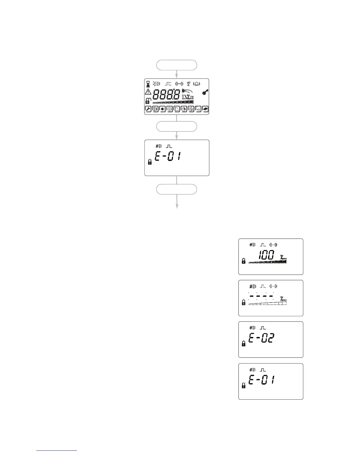
4. Apply power
• Commissioned system:
• Detectors have been found but the selected Detector is not
aligned:
• Detector is connected but not ‘Found’ (normal on
uncommissioned system):
6
• Communications fault, or no Detector connected: