- 9 -
8. Connection and Configuration Settings.
8.1. Field Wiring.
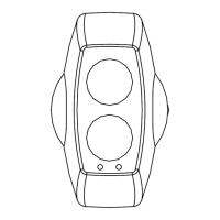
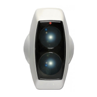
The field wiring interface is accessed through the back plate of the Detector Head (See Fig 4). The small 2-pin
connector on the left is the port for the optional Low Level Control tester. The 8-pin connector is the interface to
the field wiring and is numbered left to right. Each unit is fitted with a ‘flying’ lead, with an 8-pin connector fitted.
Relay states are shown in powered, no alarm, no fault condition. See table below :
Pin Number Wire Colour Signal Description
1 *) BROWN Fire relay normally closed (NC) connection
2 BLUE Fire relay common (COM) connection
3 YELLOW Fire relay normally open (NO) connection
4 RED Positive Supply +10.2 to +30 Vdc
5 BLACK Negative Supply
6 GREEN Fault relay normally closed (NC) connection
7 WHITE Fault relay common connection (COM) connection
8 *) ORANGE Fault relay normally open (NO) connection
*) = Not available with 6-wire cables.
8.2. DIP Switch Settings.
Access to the configuration settings is through the back plate of the Detector Head (See Fig 4 page 11). Factory default
configuration settings are marked .
Dip switch
Function 1 2 3 4
Auto Reset Fire Relay (5 seconds) ON
Latching Fire Relay OFF
Fire Relay Enable, On Compensation Limit OFF
Fire Relay Disable, On Compensation Limit
ON
50% Threshold OFF OFF
35% Threshold OFF ON
25% Threshold ON OFF
12% Threshold (Use for extreme sensitivity requirements)
ON ON
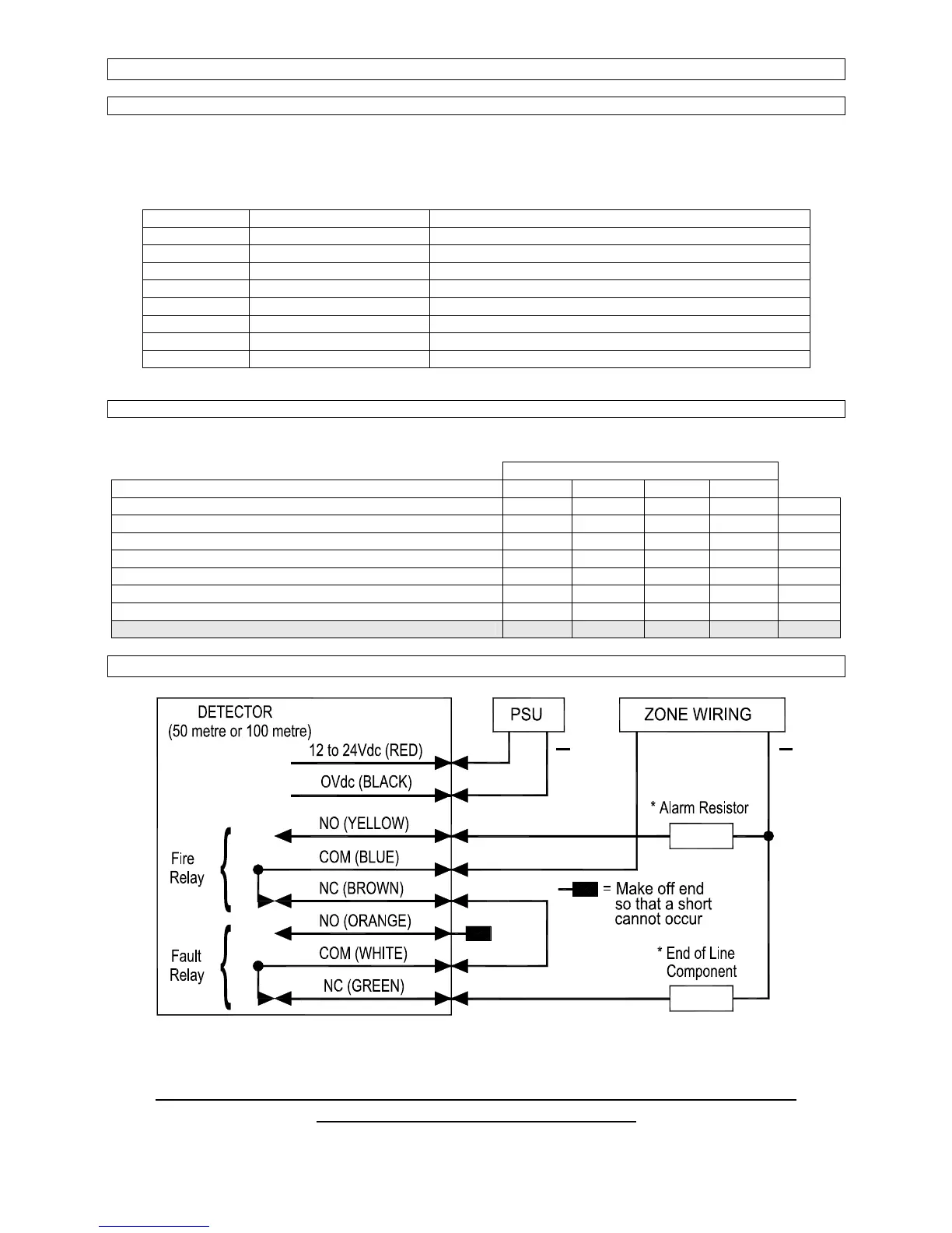
9.1 Typical single zone wiring diagram.
++
This diagram is an example for a single Detector being the only device on a zone. The operation for Fire and
Fault, should always be checked for correct connection to the panel. Relays are shown in quiescent condition.
Contact fire panel manufacturer for values of ‘Alarm Resistor’ and ‘End of Line Component’.
* These parts are not supplied with the beam.